Nissan Juke F15. Manual - part 1299


  Index      Nissan     Nissan Juke F15 (2015 year) - Service and Repair Manual


Search            


Content   ..  1297  1298  1299  1300   ..


Nissan Juke F15. Manual - part 1299


TM-386

< SYSTEM DESCRIPTION >

[CVT: RE0F10D]

SYSTEM

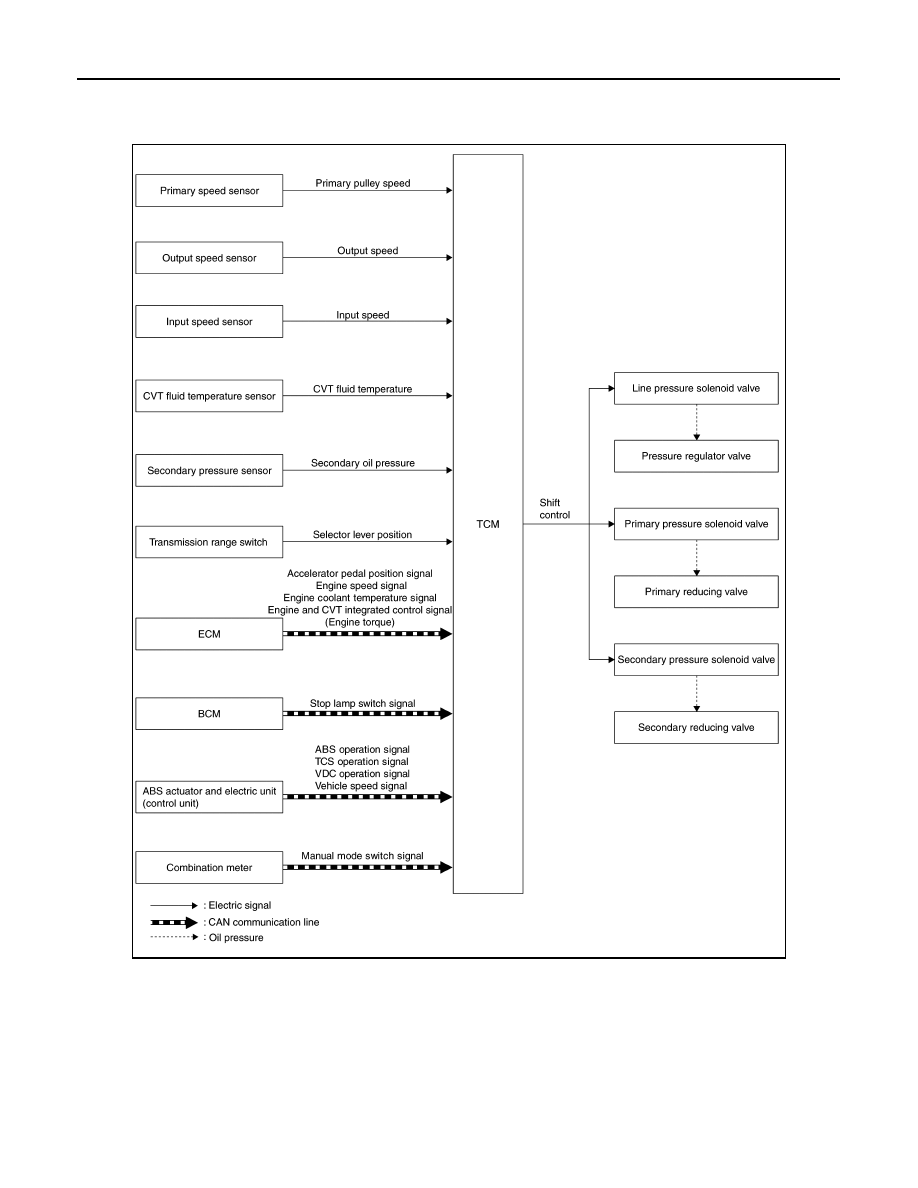
SHIFT CONTROL : System Description

INFOID:0000000012201102

SYSTEM DIAGRAM

DESCRIPTION

To select the gear ratio that can give the driving force to meet driver's intent or vehicle situation, the vehicle

driving condition such as vehicle speed or accelerator pedal position is detected and the most appropriate

gear ratio is selected and the shifting method before reaching the speed is determined. The information is out-

put to the primary pressure solenoid valve and secondary pressure solenoid valve to control the line pressure

input/output to the pulley, to determine the pulley (movable pulley) position and to control the gear position. 

Shift Position Function

• D Position (Normal)

JSDIA5313GB

SYSTEM

TM-387

< SYSTEM DESCRIPTION >

[CVT: RE0F10D]

C

E

F

G

H

I

J

K

L

M

A

B

TM

N

O

P

Gear shifting is performed in all shifting ranges from the lowest to

the highest gear ratio. 

• M Position (Manual Mode)

When the selector lever is put in the manual shift gate side, the

fixed changing gear line is set. By moving the selector lever to +

side or - side, the manual mode switch is changed over, and shift

change like M/T becomes possible following the changing gear set

line step by step.

- Manual Mode Information

The TCM transmits the manual mode shift refusal signal to the combination meter if the TCM refuses the

transmission from the driving status of vehicle when the selector lever shifts to UP side (+ side) or DOWN

side (

−side). The combination meter blinks shift indicator on the combination meter and sounds the buzzer to

indicate the driver that the shifting is not performed when receiving this signal. However, the TCM does not

transmit the manual mode shift refusal signal in the conditions as per the following.

• When the selector lever shifts to DOWN side (

− side) while driving in M1.

• When the selector lever shifts to UP (+ side) side while driving in M7.

Blipping Control

Using engine torque, the blipping control enables a faster and more responsive gear shifting by compensating

inertia torque generated from the rotational change during gear shifting in real time.

Operation 

• The blipping control is activated when shifting up/down in manual mode or when shifting up/down in “Ds”

position.

NOTE:

The blipping control is not activated when the vehicle is in the following conditions:

• When CAN communication is abnormal.

• During the retard inhibit signal transmission from ECM within the engine-CVT integrated control.

• Engine coolant temperature is less than 20

°C (68°F).

• CVT fluid temperature is more than 120

°C (248°F).

• Vehicle speed is less than 20 km/h (13 MPH).

• When ABS, TCS or VDC is active.

• During wheel spin.

• ECM selects blipping control or normal shift control according to the gear position, the selector lever posi-

tion, etc.

• The blipping control is activated when ECM judges it controllable after receiving a control permit signal from

TCM.

SCIA1953E

JSDIA4104GB

TM-388

< SYSTEM DESCRIPTION >

[CVT: RE0F10D]

SYSTEM

• ECM controls engine torque, based on generated inertia torque.

Hill Climbing And Descending Control

If a downhill is detected with the accelerator pedal is released, the system performs downshift to increase the

engine brake force so that vehicle may not be accelerated more than necessary. If a climbing hill is detected,

the system improves the acceleration performance in re-acceleration by limiting the gear shift range on the

high side. 

NOTE:

For engine brake control on a downhill, the control can be stopped with CONSULT. 

Control In Acceleration

From change of the vehicle speed or accelerator pedal position, the acceleration request level of the driver or

driving scene is evaluated. In start or acceleration during driving, the gear shift characteristics with linearity of

revolution increase and vehicle speed increase are gained to improve the acceleration feel.

• When the accelerator pedal is depressed 4/8 or more in D position, CVT performs step shifting to allow the

vehicle speed and engine speed to increase simultaneously. This improves the feel of acceleration and

enables the fuel economy by preventing unnecessary rise in engine speed, compared to the conventional

shifting.

JSDIA2841GB

JSDIA2060GB

SYSTEM

TM-389

< SYSTEM DESCRIPTION >

[CVT: RE0F10D]

C

E

F

G

H

I

J

K

L

M

A

B

TM

N

O

P

SELECT CONTROL
SELECT CONTROL : System Description

INFOID:0000000012201103

SYSTEM DIAGRAM

DESCRIPTION

Based on accelerator pedal angle, engine speed, primary pulley speed, and the input speed, the optimum

operating pressure is set to reduce impact of a selector lever operation while shifting from “N” (“P”) to “D” (“R”)

position.

LOCK-UP CONTROL

JSDIA5273GB

JSDIA3711GB


Content   ..  1297  1298  1299  1300   ..