Nissan Juke F15. Manual - part 1300


  Index      Nissan     Nissan Juke F15 (2015 year) - Service and Repair Manual


Search            


Content   ..  1298  1299  1300  1301   ..


Nissan Juke F15. Manual - part 1300


TM-390

< SYSTEM DESCRIPTION >

[CVT: RE0F10D]

SYSTEM

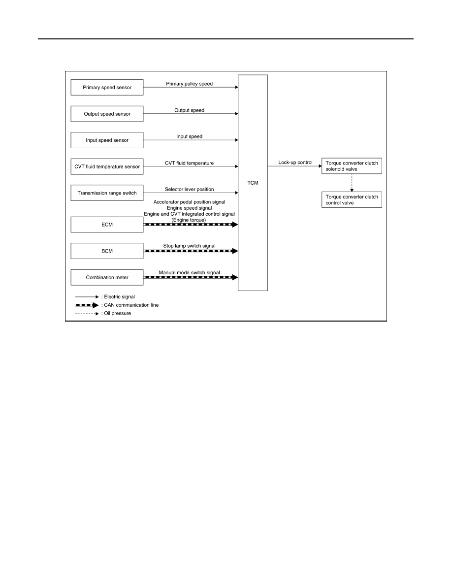
LOCK-UP CONTROL : System Description

INFOID:0000000012201104

SYSTEM DIAGRAM

DESCRIPTION

• Controls for improvement of the transmission efficiency by engaging the torque converter clutch in the

torque converter and eliminating slip of the converter. Achieves comfortable driving with slip control of the

torque converter clutch. 

• The oil pressure feed circuit for the torque converter clutch piston chamber is connected to the torque con-

verter clutch control valve. The torque converter clutch control valve is switched by the torque converter

clutch solenoid valve with the signal from TCM. This controls the oil pressure circuit, which is supplied to the

torque converter clutch piston chamber, to the release side or engagement side. 

• If the CVT fluid temperature is low or the vehicle is in fail-safe mode due to malfunction, lock-up control is

prohibited. 

Lock-up engagement 

In lock-up engagement, the torque converter clutch solenoid valve makes the torque converter clutch control

valve locked up to generate the lock-up apply pressure. This pushes the torque converter clutch piston for

engagement. 

Lock-up release condition 

In lock-up release, the torque converter clutch solenoid valve makes the torque converter clutch control valve

non-locked up to drain the lock-up apply pressure. This does not engage the torque converter clutch piston. 

INTEGRATED CONTROL SYSTEM

JSDIA5314GB

SYSTEM

TM-391

< SYSTEM DESCRIPTION >

[CVT: RE0F10D]

C

E

F

G

H

I

J

K

L

M

A

B

TM

N

O

P

INTEGRATED CONTROL SYSTEM : System Diagram

INFOID:0000000012201105

INTEGRATED CONTROL SYSTEM : System Description

INFOID:0000000012201106

• TCM receives the NORMAL mode signal, ECO mode signal or SPORT mode signal from the multi display

unit through CAN communication.

• TCM sends the recognized control mode to ECM through CAN communication (drive mode select signal). 

• With operation on the multi display unit, the mode is changed on the display, but the mode is actually not

changed due to CAN communication malfunction. 

• When the selector lever is in any position other than D position, the gear shift line is not changed according

to changes in the control mode.

CONTROL DESCRIPTION

JSDIA7197GB

TM-392

< SYSTEM DESCRIPTION >

[CVT: RE0F10D]

SYSTEM

Sport Mode Function

High Gear Ratio Limit

• Engine speed is kept higher than at D position driving, which helps to operate a “sporty” driving.

Step Shift

• Pressing down the accelerator pedal allows to drive the vehicle

with a feeling of A/T-like gear shifting.

Braking Down Shift

Control mode

Control

NORMAL mode

Driving mode that automatically selects the shift schedule considering the balance of fuel economy and 
driving performance based on the driving condition and driving trend. 

SPORT mode

Keeps high engine speed and provides direct feel and acceleration performance suitable for driving on 
winding road.
Sport mode performs the following control:
• High gear ratio limit
• Step  shift
• Braking down shift
• Acceleration off ratio hold
• Cornering ratio hold

ECO mode

Driving mode that selects the shift schedule with priority on fuel economy which gives low engine revo-
lution. 

JSDIA2893GB

JSDIA3708GB

SYSTEM

TM-393

< SYSTEM DESCRIPTION >

[CVT: RE0F10D]

C

E

F

G

H

I

J

K

L

M

A

B

TM

N

O

P

• At a moderate braking operation before corner etc., the engine speed increases according to the decelera-

tion and the transaxle shifts down automatically, in order to optimize the response at reacceleration while

providing an adequate engine braking.

Acceleration Off Ratio Hold

• When the vehicle is decelerated by quickly releasing the foot from accelerator pedal, transmission does not

shift up automatically to keep a constant gear ratio, holding the high engine speed.

When the vehicle is decelerated (by accelerator pedal OFF) in upper area of double line in below chart, the

engine speed shows a characteristic like “A”.

On the other hand, when the vehicle is decelerated (by accelerator pedal OFF) in lower area of double line in

below chart, the engine speed shows a characteristic like “B”.

Cornering Ratio Hold

• Transaxle holds gear ratio in order to keep a smooth vehicle speed during the curve and to give an adequate

driving force at the curve end.

FAIL-SAFE

If CAN communication malfunction occurs between TCM and the multi display unit, the mode when the mal-

function occurs is maintained for approximately 30 seconds and the mode is changed to NORMAL mode

when the accelerator pedal is released. 

JSDIA2894GB

JSDIA5404GB


Content   ..  1298  1299  1300  1301   ..