Nissan Juke F15. Manual - part 1293


  Index      Nissan     Nissan Juke F15 (2015 year) - Service and Repair Manual


Search            


Content   ..  1291  1292  1293  1294   ..


Nissan Juke F15. Manual - part 1293


TM-362

< SYSTEM DESCRIPTION >

[CVT: RE0F10D]

COMPONENT PARTS

NOTE:
• The following components are included in control valve assembly.
- CVT fluid temperature sensor
- Primary pressure sensor
- Secondary pressure sensor
- Line pressure solenoid valve
- Primary pressure solenoid valve
- Secondary pressure solenoid valve
- Torque converter clutch solenoid valve
- Select solenoid valve

CVT CONTROL SYSTEM : Component Description

INFOID:0000000012201070
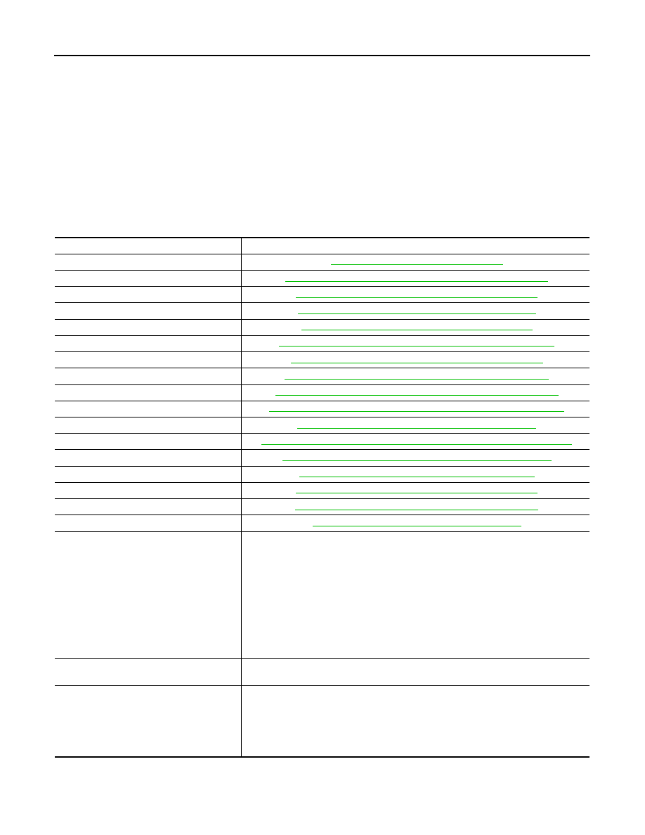
Name

Function

TCM

TM-363, "CVT CONTROL SYSTEM : TCM"

Transmission range switch

TM-363, "CVT CONTROL SYSTEM : Transmission Range Switch"

Primary speed sensor

TM-363, "CVT CONTROL SYSTEM : Primary Speed Sensor"

Output speed sensor

TM-364, "CVT CONTROL SYSTEM : Output Speed Sensor"

Input speed sensor

TM-365, "CVT CONTROL SYSTEM : Input Speed Sensor"

CVT fluid temperature sensor

TM-365, "CVT CONTROL SYSTEM : CVT Fluid Temperature Sensor"

Primary pressure sensor

TM-366, "CVT CONTROL SYSTEM : Primary Pressure Sensor"

Secondary pressure sensor

TM-366, "CVT CONTROL SYSTEM : Secondary Pressure Sensor"

Primary pressure solenoid valve

TM-366, "CVT CONTROL SYSTEM : Primary Pressure Solenoid Valve"

Secondary pressure solenoid valve

TM-367, "CVT CONTROL SYSTEM : Secondary Pressure Solenoid Valve"

Select solenoid valve

TM-367, "CVT CONTROL SYSTEM : Select Solenoid Valve"

Torque converter clutch solenoid valve

TM-367, "CVT CONTROL SYSTEM : Torque Converter Clutch Solenoid Valve"

Line pressure solenoid valve

TM-368, "CVT CONTROL SYSTEM : Line Pressure Solenoid Valve"

Manual mode switch

TM-368, "CVT CONTROL SYSTEM : Manual Mode Switch"

Shift position indicator

TM-368, "CVT CONTROL SYSTEM : Shift Position Indicator"

Manual mode indicator

TM-369, "CVT CONTROL SYSTEM : Manual Mode Indicator"

Paddle shifter

TM-369, "CVT CONTROL SYSTEM : Paddle Shifter"

ECM

Mainly transmits the following signal to TCM via CAN communication.
• Engine and CVT integrated control signal

NOTE:
General term for the communication (torque-down permission, torque-down request, 
etc.) exchanged between the ECM and TCM.

• Engine speed signal
• Engine coolant temperature signal
• Accelerator pedal position signal
• Closed throttle position signal
Mainly receives the following signal from TCM via CAN communication.
• Malfunctioning indicator lamp signal

BCM

Mainly transmits the following signal to TCM via CAN communication.
• Stop lamp switch signal

ABS actuator and electric unit (control unit)

Mainly transmits the following signals to TCM via CAN communication.
• ABS operation signal
• TCS operation signal
• VDC operation signal
• ABS malfunction signal
• Vehicle speed signal

COMPONENT PARTS

TM-363

< SYSTEM DESCRIPTION >

[CVT: RE0F10D]

C

E

F

G

H

I

J

K

L

M

A

B

TM

N

O

P

CVT CONTROL SYSTEM : TCM

INFOID:0000000012201071

• The TCM consists of a microcomputer and connectors for signal

input and output and for power supply.

• The vehicle driving status is judged based on the signals from the

sensors, switches, and other control units, and the optimal tran-

saxle control is performed.

• For TCM control items, refer to 

TM-379, "CVT CONTROL SYS-

TEM : System Description"

.

CVT CONTROL SYSTEM : Transmission Range Switch

INFOID:0000000012201072

• The transmission range switch is installed to upper part of tran-

saxle case.

• The transmission range switch detects the selector lever position.

CVT CONTROL SYSTEM : Primary Speed Sensor

INFOID:0000000012201073

• The primary speed sensor is installed to side cover of transaxle.

• The primary speed sensor detects primary pulley speed.

Combination meter

Mainly transmits the following signal to TCM via CAN communication.
• Manual mode signal
• Non-manual mode signal
• Manual mode shift up signal
• Manual mode shift down signal
Mainly receives the following signals from TCM via CAN communication.
• CVT indicator signal
• Shift position signal
• Manual mode indicator signal
• Manual mode shift refusal signal

MDU

Mainly transmits the following signal to MDU via CAN communication.
• NORMAL mode signal
• ECO mode signal
• SPORT mode signal

Name

Function

JSDIA4183ZZ

JSDIA4184ZZ

JSDIA3073ZZ

TM-364

< SYSTEM DESCRIPTION >

[CVT: RE0F10D]

COMPONENT PARTS

• The primary speed sensor generates an ON-OFF pulse signal according to the rotating body speed. TCM

judges the rotating body speed from the pulse signal.

CVT CONTROL SYSTEM : Output Speed Sensor

INFOID:0000000012201074

• The output speed sensor is installed to back side of transaxle.

• The output speed sensor detects final gear speed.

• The output speed sensor generates an ON-OFF pulse signal according to the rotating body speed. TCM

judges the rotating body speed from the pulse signal.

JSDIA1824GB

JSDIA3073ZZ

JSDIA1824GB

COMPONENT PARTS

TM-365

< SYSTEM DESCRIPTION >

[CVT: RE0F10D]

C

E

F

G

H

I

J

K

L

M

A

B

TM

N

O

P

CVT CONTROL SYSTEM : Input Speed Sensor

INFOID:0000000012201075

• The input speed sensor is installed to the front side of transaxle

case.

• The input speed sensor detects input shaft speed. 

• The input speed sensor generates an ON-OFF pulse signal according to the rotating body speed. TCM

judges the rotating body speed from the pulse signal.

CVT CONTROL SYSTEM : CVT Fluid Temperature Sensor

INFOID:0000000012201076

• The CVT fluid temperature sensor is installed to control valve.

• The CVT fluid temperature sensor detects CVT fluid temperature in oil pan.

• The fluid temperature sensor uses a thermistor, and changes the signal voltage by converting changes in the

CVT fluid temperature to a resistance value. TCM evaluates the CVT fluid temperature from the signal volt-

age value. 

JSDIA3074ZZ

JSDIA1824GB

JSDIA1825GB


Content   ..  1291  1292  1293  1294   ..