Content .. 1283 1284 1285 1286 ..
Nissan Juke F15. Manual - part 1285
TM-330
< REMOVAL AND INSTALLATION >
[CVT: RE0F10B]
CONTROL VALVE
CONTROL VALVE
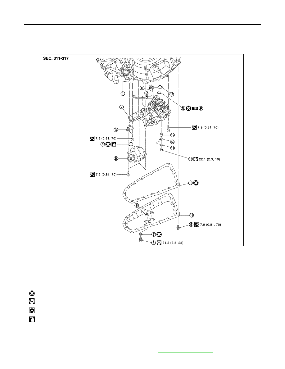
Exploded View
INFOID:0000000012201028
Removal and Installation
INFOID:0000000012201029
REMOVAL
1. Disconnect battery cable from negative terminal. Refer to
.
1.
Transaxle assembly
2.
Control valve
3.
Bracket
4.
O-ring
5.
Oil strainer assembly
6.
Magnet
7.
Drain plug gasket
8.
Drain plug
9.
Oil pan mounting bolt
10.
Oil pan
11. Oil pan gasket
12. Lock nut
13.
Washer
14. Manual plate
15. Collar
16.
Lip seal
17. Snap ring
18. Terminal cord assembly
: Always replace after every disassembly.
: N·m (kg-m, ft-lb)
: N·m (kg-m, in-lb)
: Apply CVT fluid
JSDIA2656GB