Content .. 1281 1282 1283 1284 ..
Nissan Juke F15. Manual - part 1283
TM-322
< REMOVAL AND INSTALLATION >
[CVT: RE0F10B]
PADDLE SHIFTER
PADDLE SHIFTER
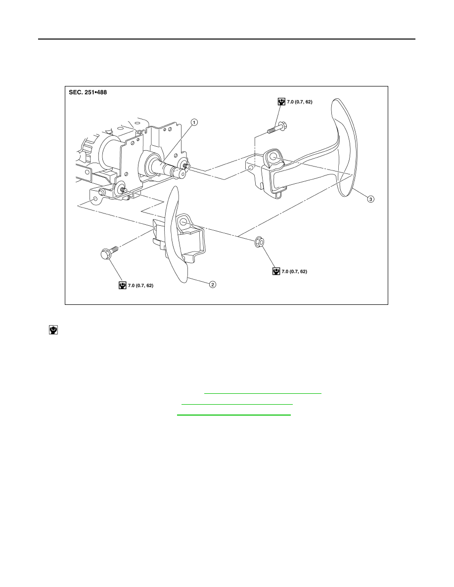
Exploded View
INFOID:0000000012201016
Removal and Installation
INFOID:0000000012201017
REMOVAL
1. Park the vehicle on a level surface.
2. Remove the driver air bag module. Refer to
SR-12, "Removal and Installation"
3. Remove the steering wheel. Refer to
ST-9, "Removal and Installation"
4. Remove the column cover. Refer to
IP-13, "Removal and Installation"
1.
Steering column assembly
2.
Paddle shifter (shift-down switch)
3.
Paddle shifter (shift-up switch)
: N·m (kg-m, in-lb)
AWDIA0557GB