Nissan Juke F15. Manual - part 1249


  Index      Nissan     Nissan Juke F15 (2015 year) - Service and Repair Manual


Search            


Content   ..  1247  1248  1249  1250   ..


Nissan Juke F15. Manual - part 1249


TM-186

< SYSTEM DESCRIPTION >

[CVT: RE0F10B]

SYSTEM

FAIL-SAFE

If CAN communication malfunction occurs between TCM and the multi display unit, the mode when the mal-

function occurs is maintained for approximately 30 seconds and the mode is changed to NORMAL mode

when the accelerator pedal is released. 

SHIFT LOCK SYSTEM
SHIFT LOCK SYSTEM : System Description

INFOID:0000000012200895

• The shift lock is the mechanism provided to prevent quick start of a vehicle by incorrect operation of a drive

when the selector lever is in P position. 

• Selector lever can be shifted from the P position to another position when the following conditions are satis-

fied.

- Ignition switch is ON.

- Stop lamp switch ON (brake pedal is depressed)

- Press the selector button. 

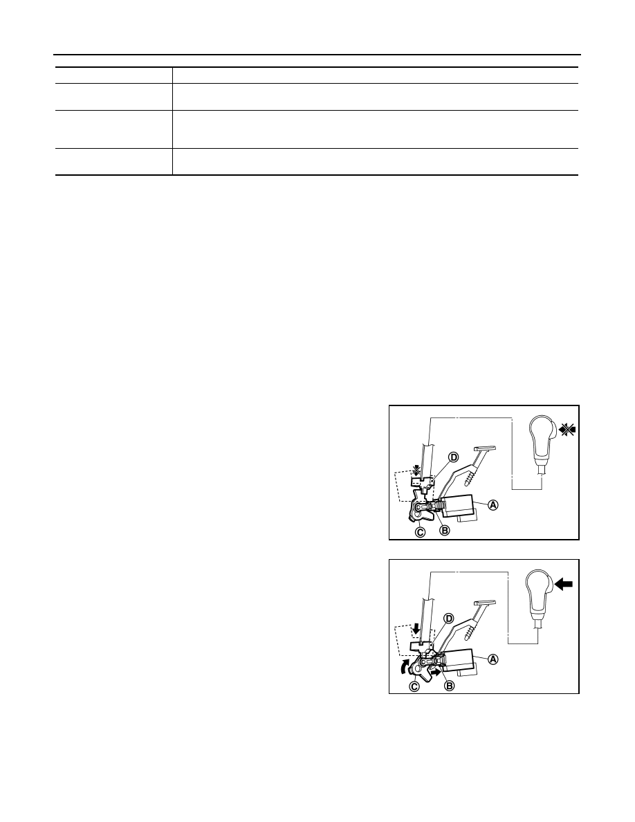
SHIFT LOCK OPERATION AT P POSITION

When brake pedal is not depressed (no selector operation allowed)

When the brake pedal is not depressed with the ignition switch ON,

the shift lock solenoid (A) is OFF (not energized) and the solenoid

rod (B) is extended with spring.

The connecting lock lever (C) is located at the position shown in the

figure when the solenoid rod is extended. It prevents the movement

of the detent rod (D). The selector lever cannot be shifted from the P

position for this reason.

When brake pedal is depressed (selector lever operation allowed)

The shift lock solenoid (A) is turned ON (energized) when the brake

pedal is depressed with the ignition switch ON. The solenoid rod (B)

is compressed with the electromagnetic force. The connecting lock

lever (C) rotates when the solenoid rod is compressed. Therefore,

the detent rod (D) can be moved. The selector lever can be shifted to

other positions for this reason.

P POSITION HOLD MECHANISM (IGNITION SWITCH LOCK)

Control mode

Control

NORMAL mode

Driving mode that automatically selects the shift schedule considering the balance of fuel economy and 
driving performance based on the driving condition and driving trend. 

SPORT mode

Keeps high engine speed and provides direct feel and acceleration performance suitable for driving on 
winding road. This driving mode also provides a rhythmical feel obtained by A/T like shifting, and pro-
duces sporty driving.

ECO mode

Driving mode that selects the shift schedule with priority on fuel economy which gives low engine revo-
lution. 

JSDIA2338ZZ

JSDIA2339ZZ

SYSTEM

TM-187

< SYSTEM DESCRIPTION >

[CVT: RE0F10B]

C

E

F

G

H

I

J

K

L

M

A

B

TM

N

O

P

The shift lock solenoid (A) is not energized when the ignition switch

is in any position other than ON. The shift mechanism is locked and

P position is held. The operation cannot be performed from P posi-

tion if the brake pedal is depressed with the ignition switch ON when

the operation system of shift lock solenoid is malfunctioning. How-

ever, the lock lever (B) is forcibly rotated and the shift lock is

released when the shift lock release button (C) is pressed from

above. The selector operation from P position can be performed. 

CAUTION:

Use the shift lock release button only when the selector lever

cannot be operated even if the brake pedal is depressed with the ignition switch ON.

KEY LOCK SYSTEM
KEY LOCK SYSTEM : System Description

INFOID:0000000012200896

KEY LOCK MECHANISM

The key is not set to LOCK when the selector lever is not selected to P position. This prevents the key from

being removed from the key cylinder.

Key lock status

The slider (B) in the key cylinder (A) is moved to the left side of the

figure when the selector lever is in any position other than P position.

The rotator (D) that rotates together with the key (C) cannot be

rotated for this reason. The key cannot be removed from the key cyl-

inder because it cannot be turned to LOCK (E).

Key unlock status

The slider (B) in the key cylinder (A) is moved to the right side of the

figure when the selector lever is in P position and the finger is

removed from the selector button. The rotator (C) can be rotated for

this reason. The key (D) can be removed from the key cylinder

because it can be turned to LOCK (E).

D

:  Detent  rod

JSDIA2340ZZ

JPDIA0108ZZ

JPDIA0109ZZ

TM-188

< SYSTEM DESCRIPTION >

[CVT: RE0F10B]

ON BOARD DIAGNOSTIC (OBD) SYSTEM

ON BOARD DIAGNOSTIC (OBD) SYSTEM

Diagnosis Description

INFOID:0000000012200897

DESCRIPTION

The CVT system has two self-diagnostic systems.

The first is the emission-related on board diagnostic system (OBD-II) performed by the TCM in combination

with the ECM. The malfunction is indicated by the MIL (malfunction indicator lamp) and is stored as a DTC in

the ECM memory, and the TCM memory.

The second is the TCM original self-diagnosis performed by the TCM. The malfunction is stored in the TCM

memory. The detected items are overlapped with OBD-II self-diagnostic items. For detail, refer to 

TM-190,

"CONSULT Function"

.

OBD-II FUNCTION

The ECM provides emission-related on board diagnostic (OBD-II) functions for the CVT system. One function

is to receive a signal from the TCM used with OBD-related parts of the CVT system. The signal is sent to the

ECM when a malfunction occurs in the corresponding OBD-related part. The other function is to indicate a

diagnostic result by means of the MIL (malfunction indicator lamp) on the instrument panel. Sensors, switches

and solenoid valves are used as sensing elements.

The MIL automatically illuminates in “One or Two Trip Detection Logic” when a malfunction is sensed in rela-

tion to CVT system parts.

ONE OR TWO TRIP DETECTION LOGIC OF OBD-II

One Trip Detection Logic

If a malfunction is sensed during the first test drive, the MIL will illuminate and the malfunction will be stored in

the ECM memory as a DTC. The TCM is not provided with such a memory function.

Two Trip Detection Logic

When a malfunction is sensed during the first test drive, it is stored in the ECM memory as a 1st trip DTC

(diagnostic trouble code) or 1st trip freeze frame data. At this point, the MIL will not illuminate. — 1st trip

If the same malfunction as that experienced during the first test drive is sensed during the second test drive,

the MIL will illuminate. — 2nd trip

The “trip” in the “One or Two Trip Detection Logic” means a driving mode in which self-diagnosis is performed

during vehicle operation.

OBD-II DIAGNOSTIC TROUBLE CODE (DTC)

How to Read DTC and 1st Trip DTC

DTC and 1st trip DTC can be read by the following methods.
(  with CONSULT or   GST) CONSULT or GST (Generic Scan Tool) Examples: P0705, P0720 etc.

These DTC are prescribed by SAE J2012.

(CONSULT also displays the malfunctioning component or system.)

• 1st trip DTC No. is the same as DTC No.

• Output of the diagnostic trouble code indicates that the indicated circuit has a malfunction. How-

ever, in case of the Mode II and GST, they do not indicate whether the malfunction is still occurring or

occurred in the past and returned to normal.

CONSULT can identify them as shown below, therefore, CONSULT (if available) is recommended.

- DTC or 1st trip DTC of a malfunction is displayed in SELF-DIAGNOSTIC RESULTS mode for “ENGINE” with

CONSULT. Time data indicates how many times the vehicle was driven after the last detection of a DTC.

- If the DTC is being detected currently, the time data will be “0”.

- If a 1st trip DTC is stored in the ECM, the time data will be “1t”.

Freeze Frame Data and 1st Trip Freeze Frame Data

• The ECM has a memory function, which stores the driving condition such as fuel system status, calculated

load value, engine coolant temperature, short term fuel trim, long term fuel trim, engine speed and vehicle

speed at the moment the ECM detects a malfunction.

Data which are stored in the ECM memory, along with the 1st trip DTC, are called 1st trip freeze frame data,

and the data, stored together with the DTC data, are called freeze frame data and displayed on CONSULT

or GST. The 1st trip freeze frame data can only be displayed on the CONSULT screen, not on the GST. For

details, refer to 

EC-84, "CONSULT Function"

.

Only one set of freeze frame data (either 1st trip freeze frame data or freeze frame data) can be stored in the

ECM. 1st trip freeze frame data is stored in the ECM memory along with the 1st trip DTC. There is no priority

ON BOARD DIAGNOSTIC (OBD) SYSTEM

TM-189

< SYSTEM DESCRIPTION >

[CVT: RE0F10B]

C

E

F

G

H

I

J

K

L

M

A

B

TM

N

O

P

for 1st trip freeze frame data, and it is updated each time a different 1st trip DTC is detected. However, once

freeze frame data (2nd trip detection/MIL on) is stored in the ECM memory, 1st trip freeze frame data is no

longer stored. Remember, only one set of freeze frame data can be stored in the ECM. The ECM has the fol-

lowing priorities to update the data.

Both 1st trip freeze frame data and freeze frame data (along with the DTC) are cleared when the ECM mem-

ory is erased.

How to Erase DTC

• The diagnostic trouble code can be erased by CONSULT, GST or ECM DIAGNOSTIC TEST MODE as

described following.

If the battery cable is disconnected, the diagnostic trouble code will be lost within 24 hours.

When you erase the DTC, using CONSULT or GST is easier and quicker than switching the mode

selector on the ECM.

• The following emission-related diagnostic information is cleared from the ECM memory when erasing DTC

related to OBD-II. For details, refer to 

EC-115, "DTC Index"

.

Diagnostic trouble codes (DTC)

1st trip diagnostic trouble codes (1st trip DTC)

Freeze frame data

1st trip freeze frame data

System readiness test (SRT) codes

Test values

 How to Erase DTC (With CONSULT)

The emission related diagnostic information in the TCM and ECM can be erased by selecting “ALL Erase” in

the “Description” of “FINAL CHECK” mode with CONSULT.

 How to Erase DTC (With GST)

1. If the ignition switch stays ON after repair work, be sure to turn ignition switch OFF once. Wait at least 10

seconds and then turn it ON (engine stopped) again.

2. Select Mode 4 with GST (Generic Scan Tool).

MALFUNCTION INDICATOR LAMP (MIL)

Description

The MIL is located on the instrument panel.
1. The MIL will light up when the ignition switch is turned ON with-

out the engine running. This is a bulb check.

• If the MIL does not light up, refer to 

EC-575, "Component

Function Check"

.

2. When the engine is started, the MIL should go off.

If the MIL remains on, the on board diagnostic system has

detected an engine system malfunction.

Priority

Items

1

Freeze frame data

Misfire — DTC: P0300 - P0304
Fuel Injection System Function — DTC: P0171, P0172

2

Except the above items (Includes CVT related items)

3

1st trip freeze frame data

JSBIA1315ZZ


Content   ..  1247  1248  1249  1250   ..