Content .. 1183 1184 1185 1186 ..
Nissan Juke F15. Manual - part 1185
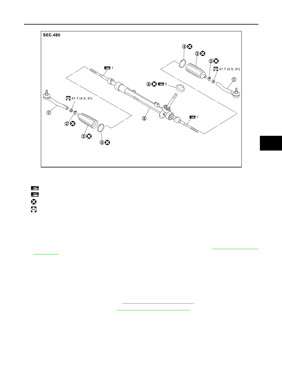
STEERING GEAR AND LINKAGE
ST-17
< REMOVAL AND INSTALLATION >
C
D
E
F
H
I
J
K
L
M
A
B
ST
N
O
P
Removal and Installation
INFOID:0000000012200348
REMOVAL
1. Set vehicle to the straight-ahead position.
2. Remove intermediate shaft mounting bolt (steering gear assembly side). Refer to
.
CAUTION:
• Spiral cable may be cut if steering wheel turns while separating steering column assembly and
steering gear assembly. Always fix the steering wheel using string to avoid turning.
• Place a matching mark on both intermediate shaft and steering gear assembly before removing
intermediate shaft.
• When removing intermediate shaft, never insert a tool, such as a screwdriver, into the yoke
groove to pull out the intermediate shaft. In case of the violation of the above, replace intermedi-
ate shaft with a new one.
3. Remove dash seal from vehicle. Refer to
ST-14, "Removal and Installation"
.
4. Remove tires with power tool. Refer to
WT-39, "Removal and Installation"
.
1.
Outer socket
2.
Boot clamp (small diameter)
3.
Boot
4.
Boot clamp (large diameter)
5.
Gear housing assembly
6.
Dust cover
1: Apply Genuine Lithium Soap, Autorex A (manufactured by Kyodo yushi) or equivalent.
2: Apply Genuine Lithium Soap, Wanlouver No.2 (manufactured by Kyodo yushi) or equivalent.
: Always replace after every disassembly.
: N·m (kg-m, ft-lb)
JPGIA0145GB