Nissan Juke F15. Manual - part 1186


  Index      Nissan     Nissan Juke F15 (2015 year) - Service and Repair Manual


Search            


Content   ..  1184  1185  1186  1187   ..


Nissan Juke F15. Manual - part 1186


SERVICE DATA AND SPECIFICATIONS (SDS)

ST-21

< SERVICE DATA AND SPECIFICATIONS (SDS) 

C

D

E

F

H

I

J

K

L

M

A

B

ST

N

O

P

SERVICE DATA AND SPECIFICATIONS (SDS)

SERVICE DATA AND SPECIFICATIONS (SDS)

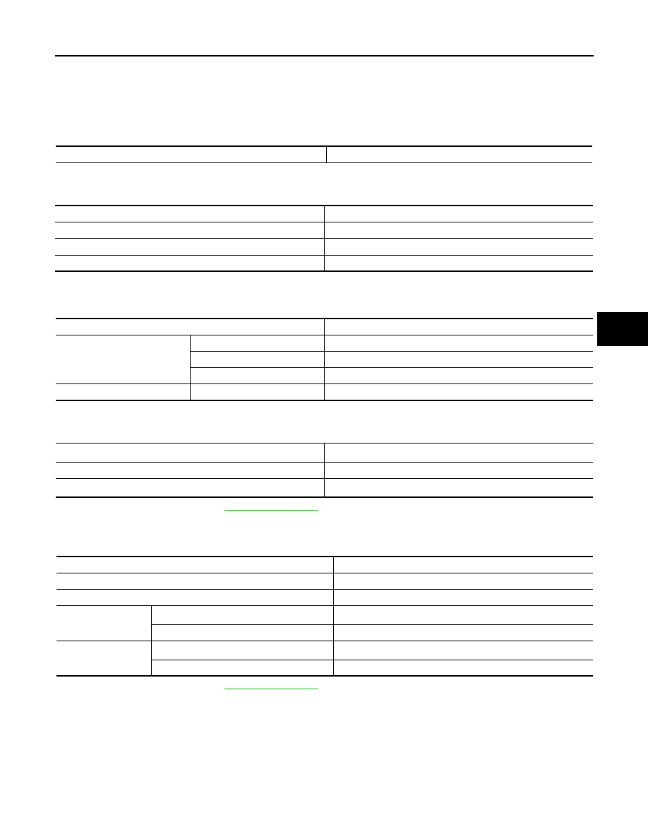
General Specifications

INFOID:0000000012200351

Steering Wheel

INFOID:0000000012200352

Steering Angle

INFOID:0000000012200353

Unit: Degree minute (Decimal degree)

Steering Column

INFOID:0000000012200354

*: For measuring position, refer to 

ST-12, "Inspection"

.

Steering Gear and Linkage

INFOID:0000000012200355

*: For measuring position, refer to 

ST-19, "Inspection"

.

Steering gear model

R25N

Item

Standard

Steering wheel axial end play

0 mm (0 in)

Steering wheel play on the outer circumference

0 - 35 mm (0 - 1.38 in)

Steering wheel turning force

36 N (3.7 kg-f, 8.09 lb-f) or less

Item

Standard

Inner wheel

Minimum

33

° 00′ (33.0°)

Nominal

36

° 00′ (36.0°)

Maximum

37

° 00′ (37.0°)

Outer wheel

Nominal

31

° 00′ (31.0°)

Tilt operating range

*

40.0 mm (1.575 in)

Rotating torque

0 – 2.1 N·m (0 – 0.21 kg-m, 0 – 2 in-lb)

Steering column length

*

438.5 – 440.5 mm (17.26 – 17.34 in)

Item

Standard

Rack stroke neutral position 

68 mm (2.68 in)

Inner socket length

83.5 mm (3.287 in)

Outer socket ball joint

Spring balance measurement

*

6.0 – 58 N (0.61 – 5.9 kg-f, 1.35 – 13.03 lb-f)

Axial end play

0.5 mm (0.020 in) or less

Inner socket ball joint

Spring balance measurement

*

4.3 – 43.1 N (0.44 – 4.39 kg-f, 0.97 – 9.68 lb-f)

Axial end play

0.2 mm (0.008 in) or less

STC-1

STEERING

C

D

E

F

H

I

J

K

L

M

SECTION 

STC

A

B

STC

N

O

P

CONTENTS

STEERING CONTROL SYSTEM

PRECAUTION ...............................................

3

PRECAUTIONS ...................................................

3

Precaution for Supplemental Restraint System 
(SRS) "AIR BAG" and "SEAT BELT PRE-TEN-
SIONER" .................................................................
..

3

Precautions for Removing Battery Terminal  .............

3

Service Notice or Precautions for EPS System  ........

4

SYSTEM DESCRIPTION  ..............................

5

COMPONENT PARTS  ........................................

5

Component Parts Location ........................................

5

Component Description .............................................

5

EPS Control Unit  .......................................................

6

EPS Motor .................................................................

6

Torque Sensor  ..........................................................

6

Reduction Gear  .........................................................

6

SYSTEM ..............................................................

7

EPS SYSTEM  ..............................................................

7

EPS SYSTEM : System Description .........................

7

EPS SYSTEM : Fail-Safe ..........................................

8

EPS SYSTEM : Protection Function .........................

8

DIAGNOSIS SYSTEM (EPS CONTROL UNIT) 

.....

9

CONSULT Function  ..................................................

9

ECU DIAGNOSIS INFORMATION  ..............

11

EPS CONTROL UNIT .........................................

11

Reference Value  .....................................................

11

Fail-Safe ..................................................................

12

Protection Function  .................................................

12

DTC Inspection Priority Chart .................................

12

DTC Index  ...............................................................

13

WIRING DIAGRAM ......................................

14

ELECTRONICALLY CONTROLLED POWER 
STEERING SYSTEM .........................................

14

Wiring Diagram ........................................................

14

BASIC INSPECTION  ...................................

18

DIAGNOSIS AND REPAIR WORKFLOW  ........

18

Work Flow ................................................................

18

Diagnostic Work Sheet  ............................................

19

DTC/CIRCUIT DIAGNOSIS  .........................

21

C1601 BATTERY POWER SUPPLY  ................

21

DTC Logic ................................................................

21

Diagnosis Procedure  ...............................................

21

C1604 TORQUE SENSOR ................................

23

DTC Logic ................................................................

23

Diagnosis Procedure  ...............................................

23

C1606 EPS MOTOR ..........................................

24

DTC Logic ................................................................

24

Diagnosis Procedure  ...............................................

24

C1607, C1608 EPS CONTROL UNIT  ...............

25

DTC Logic ................................................................

25

Diagnosis Procedure  ...............................................

25

C1609 VEHICLE SPEED SIGNAL ....................

26

DTC Logic ................................................................

26

Diagnosis Procedure  ...............................................

26

U1000 CAN COMM CIRCUIT  ...........................

27

Description ...............................................................

27

DTC Logic ................................................................

27

Diagnosis Procedure  ...............................................

27

EPS WARNING LAMP ......................................

28

Component Function Check  ....................................

28

Diagnosis Procedure  ...............................................

28

SYMPTOM DIAGNOSIS  ..............................

29

PRECAUTIONS

STC-3

< PRECAUTION >

C

D

E

F

H

I

J

K

L

M

A

B

STC

N

O

P

PRECAUTION

PRECAUTIONS

Precaution for Supplemental Restraint System (SRS) "AIR BAG" and "SEAT BELT 
PRE-TENSIONER"

INFOID:0000000012199908

The Supplemental Restraint System such as “AIR BAG” and “SEAT BELT PRE-TENSIONER”, used along

with a front seat belt, helps to reduce the risk or severity of injury to the driver and front passenger for certain

types of collision. This system includes seat belt switch inputs and dual stage front air bag modules. The SRS

system uses the seat belt switches to determine the front air bag deployment, and may only deploy one front

air bag, depending on the severity of a collision and whether the front occupants are belted or unbelted.

Information necessary to service the system safely is included in the “SRS AIR BAG” and “SEAT BELT” of this

Service Manual.

WARNING:

Always observe the following items for preventing accidental activation.

• To avoid rendering the SRS inoperative, which could increase the risk of personal injury or death in

the event of a collision that would result in air bag inflation, it is recommended that all maintenance

and repair be performed by an authorized NISSAN/INFINITI dealer.

• Improper repair, including incorrect removal and installation of the SRS, can lead to personal injury

caused by unintentional activation of the system. For removal of Spiral Cable and Air Bag Module,

see “SRS AIR BAG”.

• Never use electrical test equipment on any circuit related to the SRS unless instructed to in this Ser-

vice Manual. SRS wiring harnesses can be identified by yellow and/or orange harnesses or harness

connectors.

PRECAUTIONS WHEN USING POWER TOOLS (AIR OR ELECTRIC) AND HAMMERS

WARNING:

Always observe the following items for preventing accidental activation.

• When working near the Air Bag Diagnosis Sensor Unit or other Air Bag System sensors with the

ignition ON or engine running, never use air or electric power tools or strike near the sensor(s) with

a hammer. Heavy vibration could activate the sensor(s) and deploy the air bag(s), possibly causing

serious injury.

• When using air or electric power tools or hammers, always switch the ignition OFF, disconnect the

battery or batteries, and wait at least 3 minutes before performing any service.

Precautions for Removing Battery Terminal

INFOID:0000000012971407

When disconnecting the battery terminal, pay attention to the following.

• Always use a 12V battery as power source.

• Never disconnect battery terminal while engine is running.

• When removing the 12V battery terminal, turn OFF the ignition

switch and wait at least 30 seconds.

• For vehicles with the engine listed below, remove the battery termi-

nal after a lapse of the specified time:

NOTE:

ECU may be active for several tens of seconds after the ignition switch is turned OFF. If the battery terminal

is removed before ECU stops, then a DTC detection error or ECU data corruption may occur.

• After high-load driving, if the vehicle is equipped with the V9X engine, turn the ignition switch OFF and wait

for at least 15 minutes to remove the battery terminal.

NOTE:

D4D engine

: 20 minutes

YS23DDT

: 4 minutes

HRA2DDT

: 12 minutes

YS23DDTT

: 4 minutes

K9K engine

: 4 minutes

ZD30DDTi

: 60 seconds

M9R engine

: 4 minutes

ZD30DDTT

: 60 seconds

R9M engine

: 4 minutes

V9X engine

: 4 minutes

YD25DDTi

: 2 minutes

SEF289H


Content   ..  1184  1185  1186  1187   ..