Nissan Juke F15. Manual - part 1103


  Index      Nissan     Nissan Juke F15 (2015 year) - Service and Repair Manual


Search            


Content   ..  1101  1102  1103  1104   ..


Nissan Juke F15. Manual - part 1103


UPPER LINK

RSU-33

< REMOVAL AND INSTALLATION >

[AWD]

C

D

F

G

H

I

J

K

L

M

A

B

RSU

N

O

P

UPPER LINK

Exploded View

INFOID:0000000012200425

Removal and Installation

INFOID:0000000012200426

REMOVAL

1. Remove tires with power tool. Refer to 

WT-39, "Removal and Installation"

.

2. Remove wheel sensor and sensor harness. Refer to 

BRC-150, "REAR WHEEL SENSOR : Removal and

Installation"

.

3. Set jack under suspension arm.

CAUTION:

• Never damage the suspension arm with a jack.

• Check the stable condition when using a jack.

4. Remove eccentric disc, adjusting bolt, mounting bolt, and nut, then remove upper link.
5. Perform inspection after removal. Refer to 

RSU-34, "Inspection"

.

INSTALLATION

Note the following, and install in the reverse order of removal.

• Perform final tightening of rear suspension member and axle installation position (rubber bushing), under

unladen conditions with tires on level ground.

• Never reuse upper link mounting nut.

• Perform inspection after installation. Refer to 
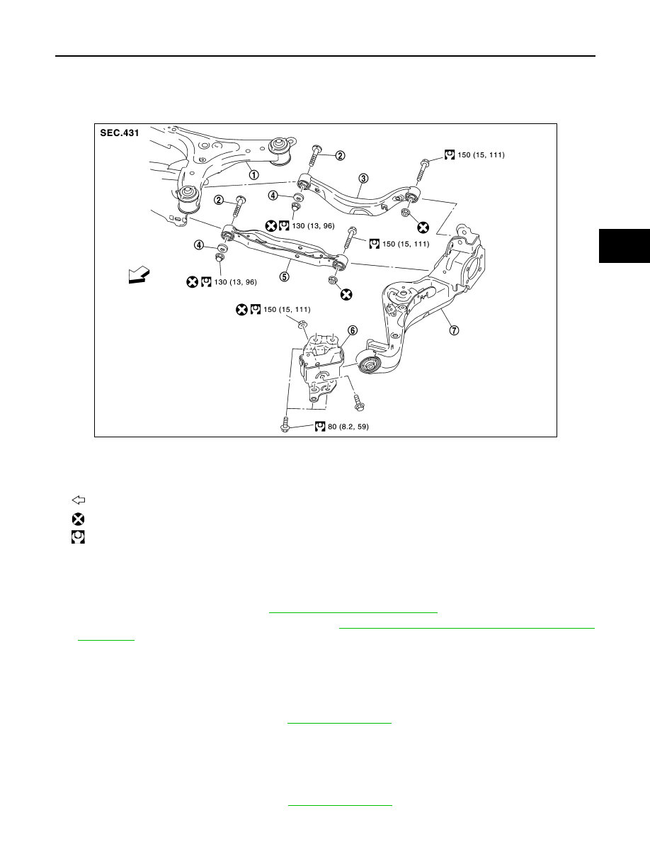
RSU-34, "Inspection"

.

1.

Rear suspension member

2.

Adjusting bolt

3.

Upper link

4.

Eccentric disk

5.

Lower link

6.

Suspension arm bracket

7.

Suspension arm

: Vehicle front

: Always replace after every disassembly.

: N·m (kg-m, ft-lb)

JPEIB0262GB

RSU-34

< REMOVAL AND INSTALLATION >

[AWD]

UPPER LINK

Inspection

INFOID:0000000012200427

INSPECTION AFTER REMOVAL

Check upper link and bushing for any deformation, cracks, or damage. Replace it if necessary.

INSPECTION AFTER INSTALLATION

1. Check wheel sensor harness for proper connection. Refer to 

BRC-148, "REAR WHEEL SENSOR :

Exploded View"

.

2. Check wheel alignment. Refer to 

RSU-22, "Inspection"

.

3. Adjust neutral position of steering angle sensor. Refer to 

BRC-63, "Work Procedure"

.

REAR STABILIZER

RSU-35

< REMOVAL AND INSTALLATION >

[AWD]

C

D

F

G

H

I

J

K

L

M

A

B

RSU

N

O

P

REAR STABILIZER

Exploded View

INFOID:0000000012200428

Removal and Installation

INFOID:0000000012200429

REMOVAL

1. Remove stabilizer link.
2. Remove center muffler. Refer to 

EX-10, "Removal and Installation"

.

3. Remove mounting nuts on stabilizer clamp, bushing, and stabilizer bar from suspension member.
4. Perform inspection after removal. Refer to 

RSU-35, "Inspection"

.

INSTALLATION

Note the following, and install in the reverse order of removal.

• Perform final tightening of rear suspension member and axle installation position (rubber bushing), under

unladen conditions with tires on level ground.

• Never reuse stabilizer link mounting nut.

Inspection

INFOID:0000000012200430

INSPECTION AFTER REMOVAL

Check stabilizer bar, stabilizer link, stabilizer bushing and stabilizer clamp for deformation, cracks or damage.

Replace it if necessary.

1.

Stabilizer bar

2.

Bushing

3.

Stabilizer clamp

4.

Stabilizer link

5.

Lower link

6.

Rear suspension member

: Vehicle front

: Always replace after every disassembly.

: N·m (kg-m, ft-lb)

JPEIB0263GB

RSU-36

< REMOVAL AND INSTALLATION >

[AWD]

REAR SUSPENSION ASSEMBLY

REAR SUSPENSION ASSEMBLY

Exploded View

INFOID:0000000012200431

Removal and Installation

INFOID:0000000012200432

REMOVAL

1. Remove tires with power tool. Refer to 

WT-39, "Removal and Installation"

.

2. Remove center muffler. Refer to 

EX-10, "Removal and Installation"

.

3. Remove propeller shaft. Refer to 

DLN-124, "Removal and Installation"

.

4. Remove stabilizer bar. Refer to 

RSU-35, "Removal and Installation"

.

5. Remove wheel sensor and sensor harness. Refer to 

BRC-150, "REAR WHEEL SENSOR : Removal and

Installation"

.

6. Remove upper link from suspension arm. Refer to 

RSU-33, "Removal and Installation"

.

7. Remove lower link from suspension arm. Refer to 

RSU-31, "Removal and Installation"

.

8. Remove drive shaft from rear final drive. Refer to 

RAX-19, "Removal and Installation"

.

9. Remove rear final drive. Refer to 

DLN-151, "Removal and Installation"

.

10. Set jack under rear suspension member.

CAUTION:

• Never damage the suspension member with a jack.

• Check the stable condition when using a jack.

11. Remove rear suspension member mounting bolts, rebound stopper, and washer.
12. Slowly lower jack, then remove rear suspension member, lower link and upper link from vehicle as a unit.

CAUTION:

Operate while checking that jack supporting status is stable.

13. Remove lower link and upper link from rear suspension member.
14. Perform inspection after removal. Refer to 

RSU-37, "Inspection"

.

INSTALLATION

Note the following, and install in the reverse order of the removal.

1.

Rear suspension member

2.

Rebound stopper

3.

Washer

: Vehicle front

: N·m (kg-m, ft-lb)

JPEIB0264GB


Content   ..  1101  1102  1103  1104   ..