Nissan Juke F15. Manual - part 1098


  Index      Nissan     Nissan Juke F15 (2015 year) - Service and Repair Manual


Search            


Content   ..  1096  1097  1098  1099   ..


Nissan Juke F15. Manual - part 1098


COIL SPRING

RSU-13

< REMOVAL AND INSTALLATION >

[2WD]

C

D

F

G

H

I

J

K

L

M

A

B

RSU

N

O

P

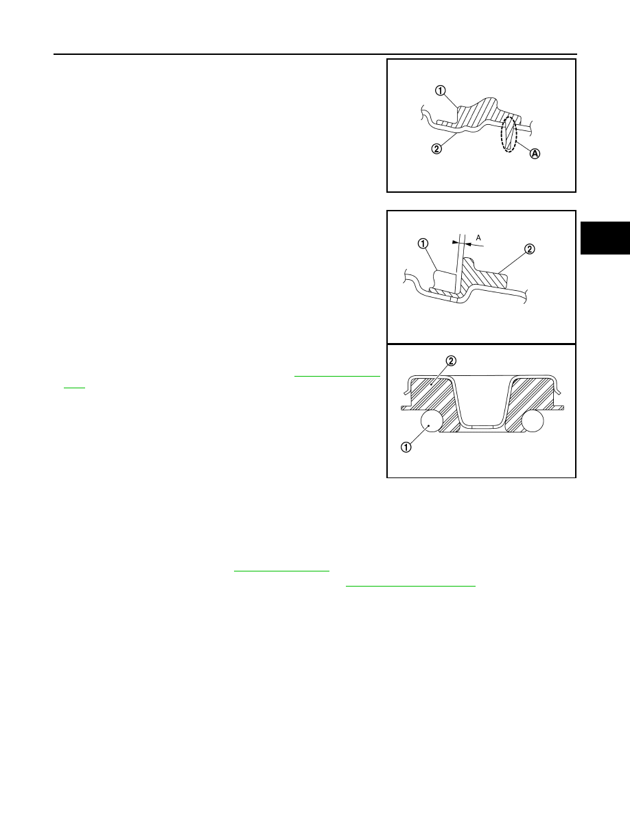
• Match up lower rubber seat (1) indentions and rear suspension

beam (2) grooves (A) and attach.

• Securely install coil spring (1) with the lower end of the major diam-

eter aligned with the steps of lower rubber seat (2).

• Install coil spring (1) by aligning upper end of coil spring with upper

seat (2) in to the protrusion of body side as shown in the figure.

• Perform inspection after installation. Refer to 

RSU-13, "Inspec-

tion"

.

Inspection

INFOID:0000000012200399

INSPECTION AFTER REMOVAL

Check rubber seat and coil spring for deformation, crack, and damage. Replace it if necessary.

INSPECTION AFTER INSTALLATION

1. Check wheel alignment. Refer to 

RSU-7, "Inspection"

.

2. Adjust neutral position of steering angle sensor. Refer to 

BRC-63, "Work Procedure"

.

JSEIA0900ZZ

Dimension (A)

: 5 mm (0.20 in) or less

JSEIA0899ZZ

JSEIA0901ZZ

RSU-14

< REMOVAL AND INSTALLATION >

[2WD]

REAR SUSPENSION BEAM

REAR SUSPENSION BEAM

Exploded View

INFOID:0000000012200400

Removal and Installation

INFOID:0000000012200401

REMOVAL

1. Remove tires with power tool. Refer to 

WT-39, "Removal and Installation"

.

2. Drain brake fluid. Refer to 

BR-12, "Draining"

.

3. Remove wheel sensor and sensor harness. Refer to 

BRC-150, "REAR WHEEL SENSOR : Removal and

Installation"

.

4. Remove brake caliper assembly. Refer to 

BR-64, "BRAKE CALIPER ASSEMBLY : Removal and Installa-

tion"

.

5. Remove disc rotor. Refer to 

RAX-7, "Removal and Installation"

.

6. Remove parking brake shoe assembly. Refer to 

PB-9, "Removal and Installation"

.

7. Remove parking brake cable from back plate and rear suspension beam. Refer to 

PB-7, "Removal and

Installation"

.

8. Separate brake hose and brake tube. Refer to 

BR-32, "REAR : Removal and Installation"

.

9. Set suitable jack under rear suspension beam.

CAUTION:

• Never damage the suspension beam with a jack.

• Check the stable condition when using a jack.

10. Remove shock absorber mounting bolts (lower side). Refer to 

RSU-9, "Removal and Installation"

.

11. Remove coil spring. Refer to 

RSU-12, "Removal and Installation"

.

12. Remove rear suspension arm bracket mounting bolts.
13. Remove rear suspension arm beam mounting bolts and nuts.
14. Slowly lower jack, remove rear suspension arm bracket and rear suspension beam from vehicle.

CAUTION:

Operate while checking that jack supporting status is stable.

15. Remove wheel hub assembly. Refer to 

RAX-7, "Removal and Installation"

.

16. Remove rear suspension arm bracket from rear suspension beam.

1.

Rear suspension beam

2.

Rear suspension arm bracket

: Always replace after every disassembly.

: N·m (kg-m, ft-lb)

JPEIB0245GB

REAR SUSPENSION BEAM

RSU-15

< REMOVAL AND INSTALLATION >

[2WD]

C

D

F

G

H

I

J

K

L

M

A

B

RSU

N

O

P

17. Perform inspection after removal. Refer to 

RSU-15, "Inspection"

.

INSTALLATION

Note the following, and install in the reverse order of removal.

• Never reuse rear suspension beam mounting nut.

• To install rear suspension arm bracket to the vehicle, temporarily

tighten the bolts before tightening to the specified torque, referring

to the tightening method and the numerical order shown below:

• Perform final tightening of rear suspension beam installation posi-

tion (rubber bushing), under unladen conditions with tires on level

ground.

• Perform inspection after installation. Refer to 

RSU-15, "Inspection"

.

Inspection

INFOID:0000000012200402

INSPECTION AFTER REMOVAL

Check rear suspension beam and rear suspension beam bracket for deformation, cracks or damage. Replace

the part if necessary.

INSPECTION AFTER INSTALLATION

1. Check wheel sensor harness for proper connection. Refer to 

BRC-148, "REAR WHEEL SENSOR :

Exploded View"

.

2. Adjust parking brake. Refer to 

PB-4, "Inspection and Adjustment"

.

3. Check wheel alignment. Refer to 

RSU-7, "Inspection"

.

4. Adjust neutral position of steering angle sensor. Refer to 

BRC-63, "Work Procedure"

.

Temporary tightening

: 1 

→ 2 → 3 → 4

Final tightening (specified torque)

: 5 

→ 6 → 3 → 4 → 1 → 2 → 7 → 8

: Vehicle front

JPEIB0247ZZ

RSU-16

< SERVICE DATA AND SPECIFICATIONS (SDS) 

[2WD]

SERVICE DATA AND SPECIFICATIONS (SDS)

SERVICE DATA AND SPECIFICATIONS (SDS)

SERVICE DATA AND SPECIFICATIONS (SDS)

Wheel Alignment

INFOID:0000000012200403

FOR USA MODELS

Measure value under unladen

*2

 conditions.

*1: Since adjustment mechanism is not included, the value of the left and right wheels (both wheels) must be

used as the standard value.

*2: Fuel, engine coolant and lubricant are full. Spare tire, jack, hand tools and mats are in designated posi-

tions. 

FOR CANADA MODELS

Measure value under unladen

*2

 conditions.

*1: Since adjustment mechanism is not included, the value of the left and right wheels (both wheels) must be

used as the standard value.

*2: Fuel, engine coolant and lubricant are full. Spare tire, jack, hand tools and mats are in designated posi-

tions. 

Wheelarch Height

INFOID:0000000012200404

FOR USA MODELS

Item

Standard

Camber
Degree minute (Decimal degree)

Minimum

−2° 01′ (−2.01°)

Nominal

−1° 31′ (−1.52°)

Maximum

−1° 01′ (−1.02°)

Toe-in

Total toe-in
Distance

Minimum

Out 1.1 mm (Out 0.043 in)

Nominal

In 2.9 mm (In 0.114 in)

Maximum

In 6.9 mm (In 0.272 in)

Toe angle (left wheel and right wheel)

*1

Degree minute (Decimal degree)

Minimum

Out 0

° 05′ 00″ (Out 0.08°)

Nominal

In 0

° 15′ 00″ (In 0.25°)

Maximum

In 0

° 35′ 00″ (In 0.58°)

Item

Standard

Camber
Degree minute (Decimal degree)

Minimum

−2° 01′ (−2.01°)

Nominal

−1° 31′ (−1.52°)

Maximum

−1° 01′ (−1.02°)

Toe-in

Total toe-in
Distance

Minimum

Out 1.2 mm (Out 0.047 in)

Nominal

In 2.8 mm (In 0.11 in)

Maximum

In 6.8 mm (In 0.268 in)

Toe angle (left wheel and right wheel)

*1

Degree minute (Decimal degree)

Minimum

Out 0

° 06′ 00″ (Out 0.10°)

Nominal

In 0

° 14′ 00″ (In 0.23°)

Maximum

In 0

° 34′ 00″ (In 0.56°)

Item

Standard

NISMO

NISMO RS

Standard

Transmission

M/T

CVT

Tire Size

17 inch

18 inch

17 inch

Front (Hf)

734 mm (28.90 in)

724 mm (28.50 in)

725 mm (28.54 in)

735 mm (28.94 in)


Content   ..  1096  1097  1098  1099   ..