Nissan Juke F15. Manual - part 1096


  Index      Nissan     Nissan Juke F15 (2015 year) - Service and Repair Manual


Search            


Content   ..  1094  1095  1096  1097   ..


Nissan Juke F15. Manual - part 1096


NOISE, VIBRATION AND HARSHNESS (NVH) TROUBLESHOOTING

RSU-5

< SYMPTOM DIAGNOSIS >

[2WD]

C

D

F

G

H

I

J

K

L

M

A

B

RSU

N

O

P

SYMPTOM DIAGNOSIS

NOISE, VIBRATION AND HARSHNESS (NVH) TROUBLESHOOTING

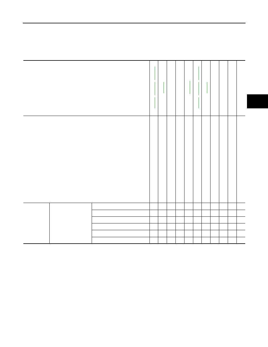
NVH Troubleshooting Chart

INFOID:0000000012200390

Use chart below to find the cause of the symptom. If necessary, repair or replace these parts.

×: Applicable

Reference

RSU-8

RSU-12

RSU-14

RSU-8

RSU-13

RSU-8

RSU-12

RSU-14

RSU-7

NVH 

in 

RAX and RSU sections

NVH in WT section

NVH in WT section

NVH in BR section

Possible cause and SUSPECTED PARTS

Imp

rop

er i

ns

ta

lla

tio

n,

 lo

os

en

es

s

Sh

oc

ab

so

rbe

r de

form

a

tio

n, 

dam

a

ge

 or d

ef

lec

tion

Bu

sh

in

g o

r m

ou

nti

ng

 de

teri

ora

tio

n

Part

s interf

erence

S

p

rin

g f

ati

gu

e

Su

sp

en

si

on

 lo

os

en

es

s

In

co

rrec

t wh

ee

l a

lig

nm

en

t

REAR A

XLE 

AND REAR SUSPE

NSION

TI

RE

ROAD WHEE

L

BRAKE

Symptom

REAR SUSPENSION

Noise

×

×

×

×

×

×

×

×

×

×

Shake

×

×

×

×

×

×

×

×

×

Vibration

×

×

×

×

×

×

×

Shimmy

×

×

×

×

×

×

×

×

×

Judder 

×

×

×

×

×

×

×

Poor quality ride or handling

×

×

×

×

×

×

×

×

×

RSU-6

< PERIODIC MAINTENANCE >

[2WD]

REAR SUSPENSION ASSEMBLY

PERIODIC MAINTENANCE

REAR SUSPENSION ASSEMBLY

Inspection

INFOID:0000000012200391

COMPONENT PART

Check the mounting conditions (looseness, backlash) of each component and component conditions (wear,

damage) are normal.

SHOCK ABSORBER ASSEMBLY

Check for oil leakage, damage, and replace if necessary.

WHEEL ALIGNMENT

RSU-7

< PERIODIC MAINTENANCE >

[2WD]

C

D

F

G

H

I

J

K

L

M

A

B

RSU

N

O

P

WHEEL ALIGNMENT

Inspection

INFOID:0000000012200392

DESCRIPTION

CAUTION:

• The adjustment mechanisms of camber and toe-in are not included.

• If camber and toe-in is outside the standard, check front suspension parts for wear and damage.

Replace suspect parts if a malfunction is detected.

Measure wheel alignment under unladen conditions. 

NOTE:

“Unladen conditions” means that fuel, engine coolant, and lubricant are full. Spare tire, jack, hand tools and

mats are in designated positions.

PRELIMINARY CHECK

Check the following:

• Tires for improper air pressure and wear. Refer to 

WT-47, "Tire Air Pressure"

.

• Road wheels for runout.

• Wheel bearing axial end play. Refer to 

RAX-6, "Inspection"

.

• Shock absorber operation.

• Each mounting point of axle and suspension for looseness and deformation.

• Each of rear suspension beam and shock absorber for cracks, deformation, and other damage.

• Vehicle height (posture).

GENERAL INFORMATION AND RECOMMENDATIONS

• A four-wheel thrust alignment should be performed.

- This type of alignment is recommended for any NISSAN/INFINITI vehicle.

- The four-wheel “thrust” process helps ensure that the vehicle is properly aligned and the steering wheel is

centered.

- The alignment rack itself should be capable of accepting any NISSAN/INFINITI vehicle.

- The rack should be checked to ensure that it is level.

• Check the machine is properly calibrated.

- Your alignment equipment should be regularly calibrated in order to give correct information.

- Check with the manufacturer of your specific equipment for their recommended Service/Calibration Sched-

ule.

ALIGNMENT PROCESS

IMPORTANT:

Use only the alignment specifications listed in this Service Manual.

• When displaying the alignment settings, many alignment machines use “indicators”: (Green/red, plus or

minus, Go/No Go). Never use these indicators.

- The alignment specifications programmed into your machine that operate these indicators may not be cor-

rect.

- This may result in an ERROR.

• Most camera-type alignment machines are equipped with both “Rolling Compensation” method and optional

“Jacking Compensation” method to “compensate” the alignment targets or head units. “Rolling Compensa-

tion” is the preferred method.

- If using the “Rolling Compensation” method, after installing the alignment targets or head units, push or pull

on the rear wheel to move the vehicle. Do not push or pull on the vehicle body.

- If using the “Jacking Compensation” method, after installing the alignment targets or head units, raise the

vehicle and rotate the wheels 1/2 turn both ways.

NOTE:

Do not use the “Rolling Compensation” method if you are using sensor-type alignment equipment.

- Follow all instructions for the alignment machine you're using for more information.

RSU-8

< REMOVAL AND INSTALLATION >

[2WD]

REAR SHOCK ABSORBER

REMOVAL AND INSTALLATION

REAR SHOCK ABSORBER

Exploded View

INFOID:0000000012200393

EXCEPT FOR 18 INCH TIRE

FOR 18 INCH TIRE

1.

Rear suspension beam

2.

Shock absorber

3.

Bound bumper

4.

Bound bumper cover

5.

Washer

6.

Bushing

7.

Distance tube

8.

Piston rod lock nut

9.

Cap

: Always replace after every disassembly.

: N·m (kg-m, ft-lb)

JPEIB0238GB

1.

Rear suspension beam

2.

Shock absorber

3.

Bound bumper

4.

Bound bumper cover

5.

Washer

6.

Bushing

7.

Distance tube

8.

Piston rod lock nut

9.

Cap

JSEIA0686GB


Content   ..  1094  1095  1096  1097   ..