Nissan Juke F15. Manual - part 1082


  Index      Nissan     Nissan Juke F15 (2015 year) - Service and Repair Manual


Search            


Content   ..  1080  1081  1082  1083   ..


Nissan Juke F15. Manual - part 1082


RAX-20

< REMOVAL AND INSTALLATION >

[AWD]

REAR DRIVE SHAFT

CAUTION:

• Never damage the suspension arm with a jack.

• Check the stable condition when using a jack.

9. Remove stabilizer link. Refer to 

RSU-35, "Removal and Installation"

.

10. Remove shock absorber from suspension arm. Refer to 

RSU-24, "Removal and Installation"

.

11. Remove upper link from suspension arm. Refer to 

RSU-33, "Removal and Installation"

.

12. Remove lower link from suspension arm. Refer to 

RSU-31, "Removal and Installation"

.

13. Remove drive shaft from final drive assembly.

CAUTION:

Confirm that the circular clip is attached to the drive shaft.

14. Perform inspection after removal. Refer to 

RAX-25, "Inspection"

.

INSTALLATION

Note the following, and install in the reverse order of removal.

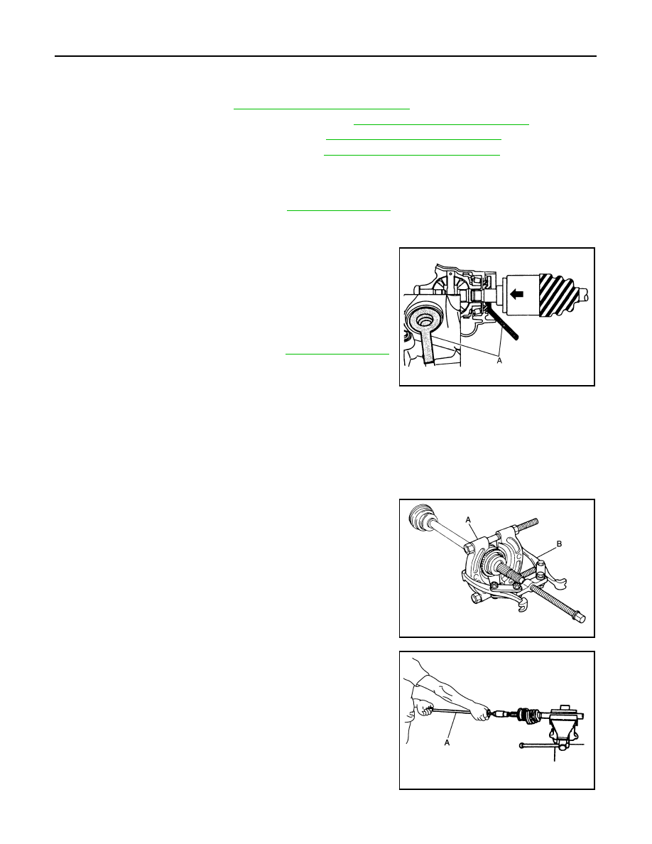
• Place the protector (A) [SST:KV38107900 ( — )] onto final drive

assembly to prevent damage to the oil seal while inserting drive

shaft. Slide drive shaft sliding joint and tap with a hammer to install

securely.

CAUTION:

Check that circular clip is completely engaged.

• Perform final tightening of bolts and nuts at suspension arm (rub-

ber bushing), under unladen conditions with tires on level ground.

• Perform inspection after installation. Refer to 

RAX-25, "Inspection"

.

WHEEL SIDE
WHEEL SIDE : Disassembly and Assembly

INFOID:0000000012196566

DISASSEMBLY

1. Fix shaft with a vise.

CAUTION:

Protect shaft using aluminum or copper plates when fixing with a vise.

2. If sensor rotor needs to be removed, use a bearing replacer (A)

and puller (B).

3. Remove boot bands. Then remove boot from joint sub-assem-

bly.

4. Screw drive shaft puller (A) (commercial service tool) into joint

sub-assembly screw part to a length of 30 mm (1.18 in) or more.

Support drive shaft with one hand and pull out joint sub-assem-

bly from shaft.

CAUTION:

• Align drive shaft puller and drive shaft and remove them

by pulling firmly and uniformly.

• If joint sub-assembly cannot be removed after five or

more unsuccessful attempts, replace shaft and joint sub

assembly as a set.

5. Remove circular clip from shaft.
6. Remove boot from shaft.

JPDIF0023ZZ

JPDIG0016ZZ

JPDIG0151ZZ

REAR DRIVE SHAFT

RAX-21

< REMOVAL AND INSTALLATION >

[AWD]

C

E

F

G

H

I

J

K

L

M

A

B

RAX

N

O

P

7. Perform inspection after disassembly. Refer to 

RAX-25, "Inspection"

.

ASSEMBLY

1. If sensor rotor (1) is removed, use a drift (A) [SST:KV38100500 (

— )] and color (B) [SST:KV40101840 ( — )] to press in a new

one.

CAUTION:

Never reuse sensor rotor.

2. Clean the old grease on joint sub-assembly with paper waste.

3. Fill serration slot joint sub-assembly (1) with NISSAN genuine

grease or equivalent until the serration slot and ball groove

become full to the brim.

CAUTION:

After applying grease, use a shop cloth to wipe off old

grease that has oozed out.

4. Install boot and boot bands to shaft.

CAUTION:

• Wrap serration on shaft with tape (A) to protect the boot

from damage.

• Never reuse boot and boot band.

5. Remove the tape wrapped around the serrated on shaft.

6. Position the circular clip (1) on groove at the shaft edge.

CAUTION:

Never reuse circular clip.

NOTE:

Drive joint inserter is recommended when installing circular clip.

7. Align both center axles of the shaft edge and joint sub-assembly.

Then assemble shaft with joint sub-assembly holding circular

clip.

PDIA1182J

JPDIF0008ZZ

JPDIF0009ZZ

JPDIF0305ZZ

RAX-22

< REMOVAL AND INSTALLATION >

[AWD]

REAR DRIVE SHAFT

8. Install joint sub-assembly to shaft using plastic hammer.

CAUTION:

• Check circular clip is properly positioned on groove of the

joint sub-assembly.

• Confirm that joint sub-assembly is correctly engaged

while rotating drive shaft.

9. Apply the specified amount of grease into the boot inside from

large diameter side of boot.

10. Install the boot securely into grooves (indicated by “*” marks)

shown in the figure.

CAUTION:

If grease adheres to the boot mounting surface (indicated

by “*” mark) on the shaft or joint sub-assembly, boot may

be removed. Remove all grease from the boot mounting

surface.

11. To prevent the deformation of the boot, adjust the boot installa-

tion length (L) to the specified value shown below by inserting

the suitable tool into inside of the boot from the large diameter

side of the boot and discharging the inside air.

CAUTION:

• If the boot installation length exceeds the standard, it may cause breakage of the boot.

• Be careful not to touch the inside of the boot with a tip of tool.

12. Install boot bands securely.

CAUTION:

Never reuse boot band.

Small boot band

• Secure the ends of the boot with boot bands using the boot

band crimping tool (A) [SST:KV40107300 ( — )].

CAUTION:

Secure boot band so that dimension (M) meets the speci-

fication as shown in the figure.

Large boot band

Grease amount

: Refer to 

RAX-26, "Drive Shaft"

.

RAC0049D

L : Refer to 

RAX-26, "Drive Shaft"

.

JPDIG0136ZZ

PDIA1187J

M

: 1.0 – 4.0 mm (0.039 – 0.157 in)

DSF0047D

REAR DRIVE SHAFT

RAX-23

< REMOVAL AND INSTALLATION >

[AWD]

C

E

F

G

H

I

J

K

L

M

A

B

RAX

N

O

P

1. Put boot band in the groove on drive shaft boot. Then fit

pawls (

) into holes to temporary installation.

NOTE:

For the large diameter side, fit projection (A) and guide slit

(B) at first.

2. Pinch projection on the band with suitable pliers to tighten

band.

3. Insert tip of band below end of the pawl.

13. Secure housing and shaft, and then make sure that they are in

the correct position when rotating boot. Reinstall them using

boot bands when boot installation positions become incorrect.

CAUTION:

Never reuse boot band.

FINAL DRIVE SIDE
FINAL DRIVE SIDE : Disassembly and Assembly

INFOID:0000000012196567

DISASSEMBLY

1. Fix shaft with a vise.

CAUTION:

Protect shaft using aluminum or copper plates when fixing with a vise.

2. Remove circular clip from housing.
3. Remove dust shield from housing.
4. Remove boot bands, and then remove boot from housing.
5. Put matching marks on housing and shaft. 

CAUTION:

Use paint or an equivalent for matching marks. Never scratch the surfaces.

6. Remove stopper ring with suitable tool, and pull out housing.
7. Put matching marks on ball cage/steel ball/inner race assembly

and shaft.

CAUTION:

Use paint or similar substance for matching marks. Never

scratch the surface.

SDIA3557E

SDIA3558E

JPDIG0177ZZ


Content   ..  1080  1081  1082  1083   ..