Nissan Juke F15. Manual - part 102


  Index      Nissan     Nissan Juke F15 (2015 year) - Service and Repair Manual


Search            


Content   ..  100  101  102  103   ..


Nissan Juke F15. Manual - part 102


BR-68

< SERVICE DATA AND SPECIFICATIONS (SDS) 

SERVICE DATA AND SPECIFICATIONS (SDS)

SERVICE DATA AND SPECIFICATIONS (SDS)

SERVICE DATA AND SPECIFICATIONS (SDS)

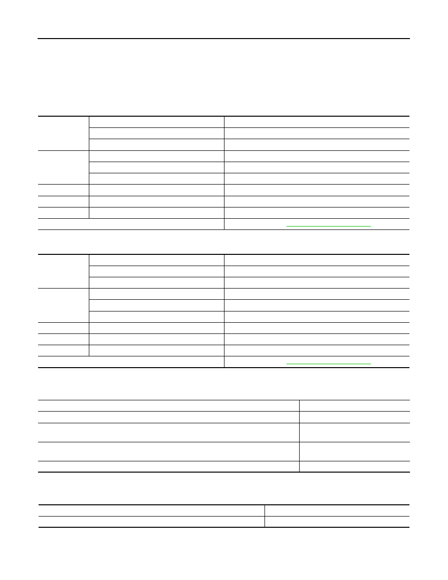
General Specifications

INFOID:0000000012200311

EXCEPT NISMO RS

Unit: mm (in)

NISMO RS

Unit: mm (in)

Brake Pedal

INFOID:0000000012200312

Unit: mm (in)

Brake Booster

INFOID:0000000012200313

Unit: mm (in)

Front Disc Brake

INFOID:0000000012200314

EXCEPT NISMO RS

Front brake

Cylinder bore diameter

57.2 (2.252)

Pad length 

× width × thickness

126.0 

× 46.0 × 11.0 (4.96 × 1.811 × 0.433)

Rotor outer diameter 

× thickness

296 

× 26.0 (11.65 × 1.024)

Rear brake 

Cylinder bore diameter

34.93 (1.3752)

Pad length 

× width × thickness

83.0 

× 31.9 × 8.5 (3.268 × 1.256 × 0.335)

Rotor outer diameter 

× thickness

292 

× 9.0 (11.50 × 0.354)

Master cylinder

Cylinder bore diameter

23.8 (15/16)

Control valve

Valve type

Electric brake force distribution

Brake booster

Diaphragm diameter

256 (10)

Recommended brake fluid

Refer to 

MA-11, "Fluids and Lubricants"

.

Front brake

Cylinder bore diameter

57.15 (2.2500)

Pad length 

× width × thickness

123.6 

× 47.5 × 11.0 (4.87 × 1.870 × 0.433)

Rotor outer diameter 

× thickness

320 

× 28.0 (12.60 × 1.102)

Rear brake 

Cylinder bore diameter

34.93 (1.3752)

Pad length 

× width × thickness

83.0 

× 31.9 × 8.5 (3.268 × 1.256 × 0.335)

Rotor outer diameter 

× thickness

292 

× 16.0 (11.50 × 0.630)

Master cylinder

Cylinder bore diameter

23.8 (15/16)

Control valve

Valve type

Electric brake force distribution

Brake booster

Diaphragm diameter

256 (10)

Recommended brake fluid

Refer to 

MA-11, "Fluids and Lubricants"

.

Item

Standard

Brake pedal height

160.4 – 170.4 (6.31 – 6.71)

Depressed brake pedal height
[Depressing 490 N (50 kg, 110 lb) while turning the engine ON]

70.0 (2.756) or more

Clearance between stop lamp switch and brake pedal position switch threaded end and the 
brake pedal lever

0.74 – 1.96 (0.0291 – 0.0772)

Brake pedal play

3 – 11 (0.12 – 0.43)

Item

Standard

Input rod length

156.5 – 157.5 (6.16 – 6.20)

SERVICE DATA AND SPECIFICATIONS (SDS)

BR-69

< SERVICE DATA AND SPECIFICATIONS (SDS) 

C

D

E

G

H

I

J

K

L

M

A

B

BR

N

O

P

Unit: mm (in)

*To check if rotor imbalance, rotor runout deformation is occured.

NISMO RS

Unit: mm (in)

*To check if rotor imbalance, rotor runout deformation is occured.

Rear Disc Brake

INFOID:0000000012200315

EXCEPT NISMO RS

Unit: mm (in)

*To check if rotor imbalance, rotor runout deformation is occured.

NISMO RS

Unit: mm (in)

*To check if rotor imbalance, rotor runout deformation is occured.

Item

Limit

Brake pad

Wear thickness

2.0 (0.079)

Disc rotor

Wear thickness

24.0 (0.945)

Thickness variation (measured at 8 positions)*

0.008 (0.0003)

Runout (with it attached to the vehicle)

0.035 (0.0014)

Item

Limit

Brake pad

Wear thickness

2.0 (0.079)

Disc rotor

Wear thickness

26.0 (1.024)

Thickness variation (measured at 8 positions)*

0.008 (0.0003)

Runout (with it attached to the vehicle)

0.035 (0.0014)

Item

Limit

Brake pad

Wear thickness

2.0 (0.079)

Disc rotor

Wear thickness

8.0 (0.315)

Thickness variation (measured at 8 positions)*

0.016 (0.0006)

Runout (with it attached to the vehicle)

0.1 (0.004)

Item

Limit

Brake pad

Wear thickness

2.0 (0.079)

Disc rotor

Wear thickness

14.0 (0.551)

Thickness variation (measured at 8 positions)*

0.016 (0.0006)

Runout (with it attached to the vehicle)

0.1 (0.004)

BRC-1

BRAKES

C

D

E

G

H

I

J

K

L

M

SECTION 

BRC

A

B

BRC

N

O

P

CONTENTS

BRAKE CONTROL SYSTEM

WITH VDC

PRECAUTION ...............................................

4

PRECAUTIONS ...................................................

4

Precaution for Supplemental Restraint System 
(SRS) "AIR BAG" and "SEAT BELT PRE-TEN-
SIONER" .................................................................
..

4

Precaution for Procedure without Cowl Top Cover 

......

4

Precautions for Removing Battery Terminal  .............

4

Precaution for Brake System  ....................................

5

Precaution for Brake Control system  ........................

6

Precaution for Harness Repair ..................................

7

PREPARATION ............................................

8

PREPARATION ...................................................

8

Special Service Tool  .................................................

8

Commercial Service Tool  ..........................................

8

SYSTEM DESCRIPTION  ..............................

9

COMPONENT PARTS  ........................................

9

Component Parts Location ........................................

9

Component Description ...........................................

11

Wheel Sensor and Sensor Rotor  ............................

11

ABS Actuator and Electric Unit (Control Unit)  .........

12

Stop Lamp Switch  ...................................................

13

Brake Pedal Position Switch  ...................................

13

Steering Angle Sensor  ............................................

13

Yaw Rate/Side/Decel G Sensor  ..............................

13

VDC OFF Switch .....................................................

13

Brake Fluid Level Switch .........................................

13

Parking Brake Switch  ..............................................

13

SYSTEM .............................................................

14

System Description  .................................................

14

Fail-safe ..................................................................

25

VDC FUNCTION  ........................................................

28

VDC FUNCTION : System Description  ...................

28

TCS FUNCTION .........................................................

31

TCS FUNCTION : System Description ....................

32

ABS FUNCTION  ........................................................

33

ABS FUNCTION : System Description ....................

33

EBD FUNCTION  ........................................................

35

EBD FUNCTION : System Description ....................

35

BRAKE LIMITED SLIP DIFFERENTIAL (BLSD) 
FUNCTION .................................................................

36

BRAKE LIMITED SLIP DIFFERENTIAL (BLSD) 
FUNCTION : System Description  ............................

36

DIAGNOSIS SYSTEM [ABS ACTUATOR 
AND ELECTRIC UNIT (CONTROL UNIT)] .......

39

CONSULT Function .................................................

39

ECU DIAGNOSIS INFORMATION ..............

44

ABS ACTUATOR AND ELECTRIC UNIT 
(CONTROL UNIT)  .............................................

44

Reference Value ......................................................

44

Fail-safe ...................................................................

46

DTC Inspection Priority Chart ..................................

49

DTC Index  ...............................................................

50

WIRING DIAGRAM ......................................

52

BRAKE CONTROL SYSTEM  ...........................

52

Wiring Diagram ........................................................

52

BASIC INSPECTION  ...................................

59

DIAGNOSIS AND REPAIR WORK FLOW  .......

59

Work Flow ................................................................

59

Diagnostic Work Sheet  ............................................

60

ADDITIONAL SERVICE WHEN REPLACING 
ABS ACTUATOR AND ELECTRIC UNIT 
(CONTROL UNIT)  .............................................

62

Description ...............................................................

62

BRC-2

ADJUSTMENT OF STEERING ANGLE SEN-
SOR NEUTRAL POSITION  ...............................

63

Description ..............................................................

63

Work Procedure ......................................................

63

DTC/CIRCUIT DIAGNOSIS .........................

65

C1101, C1102, C1103, C1104 WHEEL SEN-
SOR ....................................................................

65

DTC Logic ...............................................................

65

Diagnosis Procedure  ..............................................

66

C1105, C1106, C1107, C1108 WHEEL SEN-
SOR ....................................................................

70

DTC Logic ...............................................................

70

Diagnosis Procedure  ..............................................

71

C1109 POWER AND GROUND SYSTEM .........

77

DTC Logic ...............................................................

77

Diagnosis Procedure  ..............................................

77

C1110, C1170 ABS ACTUATOR AND ELEC-
TRIC UNIT (CONTROL UNIT)  ...........................

79

DTC Logic ...............................................................

79

Diagnosis Procedure  ..............................................

79

C1111 ABS MOTOR, MOTOR RELAY SYS-
TEM ....................................................................

81

DTC Logic ...............................................................

81

Diagnosis Procedure  ..............................................

81

C1113, C1145, C1146 YAW RATE/SIDE/DE-
CEL G SENSOR  ................................................

84

DTC Logic ...............................................................

84

Diagnosis Procedure  ..............................................

85

C1115 WHEEL SENSOR ...................................

88

DTC Logic ...............................................................

88

Diagnosis Procedure  ..............................................

88

C1116 STOP LAMP SWITCH ............................

95

DTC Logic ...............................................................

95

Diagnosis Procedure  ..............................................

96

Component Inspection ............................................

99

C1120, C1122, C1124, C1126 ABS IN VALVE 
SYSTEM ...........................................................

100

DTC Logic ..............................................................

100

Diagnosis Procedure  .............................................

100

C1121, C1123, C1125, C1127 ABS OUT 
VALVE SYSTEM ..............................................

102

DTC Logic ..............................................................

102

Diagnosis Procedure  .............................................

102

C1130 ENGINE SIGNAL  .................................

104

DTC Logic ..............................................................

104

Diagnosis Procedure  .............................................

104

C1140 ACTUATOR RELAY SYSTEM .............

106

DTC Logic ..............................................................

106

Diagnosis Procedure .............................................

106

C1143 STEERING ANGLE SENSOR  ..............

108

DTC Logic  .............................................................

108

Diagnosis Procedure .............................................

108

C1144 INCOMPLETE STEERING ANGLE 
SENSOR ADJUSTMENT  .................................

111

DTC Logic  .............................................................

111

Diagnosis Procedure .............................................

111

C1155 BRAKE FLUID LEVEL SWITCH  ..........

113

DTC Logic  .............................................................

113

Diagnosis Procedure .............................................

113

Component Inspection  ..........................................

116

C1164, C1165 CV SYSTEM  .............................

117

DTC Logic  .............................................................

117

Diagnosis Procedure .............................................

117

C1166, C1167 SV SYSTEM  .............................

119

DTC Logic  .............................................................

119

Diagnosis Procedure .............................................

119

C1176 STOP LAMP SW2 .................................

121

DTC Logic  .............................................................

121

Diagnosis Procedure .............................................

122

Component Inspection  ..........................................

125

U1000 CAN COMM CIRCUIT ...........................

126

Description ............................................................

126

DTC Logic  .............................................................

126

Diagnosis Procedure .............................................

126

U1010 CONTROL UNIT (CAN)  ........................

127

Description ............................................................

127

DTC Logic  .............................................................

127

Diagnosis Procedure .............................................

127

POWER SUPPLY AND GROUND CIRCUIT ....

129

Diagnosis Procedure .............................................

129

PARKING BRAKE SWITCH .............................

132

Component Function Check  .................................

132

Diagnosis Procedure .............................................

132

Component Inspection  ..........................................

132

VDC OFF SWITCH  ...........................................

134

Component Function Check  .................................

134

Diagnosis Procedure .............................................

134

Component Inspection  ..........................................

135

ABS WARNING LAMP .....................................

136

Component Function Check  .................................

136

Diagnosis Procedure .............................................

136

BRAKE WARNING LAMP ................................

137

Component Function Check  .................................

137

Diagnosis Procedure .............................................

137

VDC WARNING LAMP .....................................

138

Component Function Check  .................................

138


Content   ..  100  101  102  103   ..