Nissan Juke F15. Manual - part 101


  Index      Nissan     Nissan Juke F15 (2015 year) - Service and Repair Manual


Search            


Content   ..  99  100  101  102   ..


Nissan Juke F15. Manual - part 101


BR-64

< REMOVAL AND INSTALLATION >

REAR DISC BRAKE

BRAKE CALIPER ASSEMBLY : Removal and Installation

INFOID:0000000012200308

REMOVAL

WARNING:

Since dust covering the rear brake has an affect on human body, the dust must be removed with a

dust collector. Never splatter the dust with an air blow gun.

CAUTION:

• Never spill or splash brake fluid on painted surfaces. Brake fluid may seriously damage paint. Wipe it

out immediately and wash with water if it gets on a protect surface. For brake component parts,

never wash them with water.

• Never depress the brake pedal while removing the brake hose. If this is not complied with, brake

fluid may splash.

• Never drop removed parts.

• If the brake fluid or grease adheres to the disc rotor, quickly wipe it off.
1. Remove tires with power tool.
2. Fix the disc rotor using wheel nuts.
3. Drain brake fluid. Refer to 

BR-12, "Draining"

.

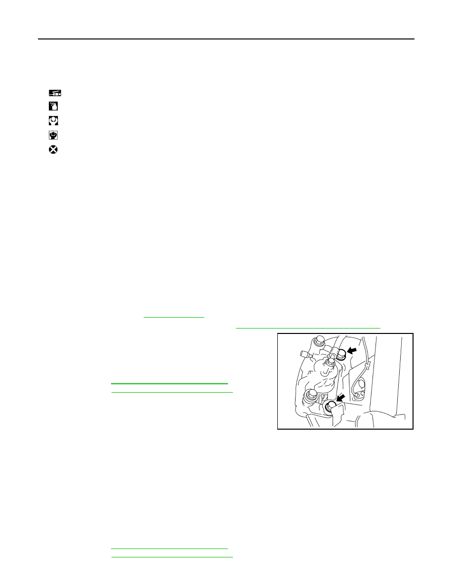
4. Separate brake hose from caliper assembly. Refer to 

BR-32, "REAR : Removal and Installation"

.

5. Remove torque member mounting bolts, and remove brake cali-

per assembly.

CAUTION:

Never drop brake pad and caliper assembly.

6. When removing disc rotor.

• 2WD: Refer to 

RAX-7, "Removal and Installation"

.

• AWD: Refer to 

RAX-16, "Removal and Installation"

.

INSTALLATION

WARNING:

Since dust covering the rear brake has an affect on human body, the dust must be removed with a

dust collector. Never splatter the dust with an air blow gun.

CAUTION:

• Never spill or splash brake fluid on painted surfaces. Brake fluid may seriously damage paint. Wipe it

out immediately and wash with water if it gets on a protect surface. For brake component parts,

never wash them with water.

• Never depress the brake pedal while removing the brake hose. If this is not complied with, brake

fluid may splash.

• If the brake fluid or grease adheres to the disc rotor, quickly wipe it off.
1. Install disc rotor.

• 2WD: Refer to 

RAX-7, "Removal and Installation"

.

• AWD: Refer to 

RAX-16, "Removal and Installation"

.

1.

Sliding pin bolt

2.

Bushing

3.

Cap

4.

Bleeder valve

5.

Cylinder body

6.

Piston seal

7.

Piston

8.

Piston boot

9.

Sliding pin boot

10. Torque member

: Apply rubber grease.

: Apply brake fluid.

: N·m (kg-m, ft-lb)

: N·m (kg-m, in-lb)

: Always replace after every disassembly.

JSFIA0495ZZ

REAR DISC BRAKE

BR-65

< REMOVAL AND INSTALLATION >

C

D

E

G

H

I

J

K

L

M

A

B

BR

N

O

P

2. Install the brake caliper assembly to the axle housing and

tighten the torque member mounting bolts to the specified

torque.

CAUTION:

Never spill or splash any grease and moisture on the brake

caliper assembly mounting face, threads, mounting bolts

and washers. Wipe out any grease and moisture.

3. Install brake hose. Refer to 

BR-32, "REAR : Removal and Instal-

lation"

.

4. Perform the air bleeding. Refer to 

BR-13, "Bleeding Brake Sys-

tem"

.

5. Check a drag of rear disc brake. If any drag is found, refer to

BR-62, "BRAKE PAD : Inspection"

.

6. Install tires. Refer to 

WT-39, "Removal and Installation"

.

7. Perform inspection after installation. Refer to 

BR-67, "BRAKE CALIPER ASSEMBLY : Inspection"

.

BRAKE CALIPER ASSEMBLY : Disassembly and Assembly

INFOID:0000000012200309

DISASSEMBLY

NOTE:

Never remove the torque member, brake pad and pad retainers when disassembling and assembling the cyl-

inder body.
1. Remove the sliding pin bolt, and remove the cylinder body from the torque member. Refer to 

BR-60,

"BRAKE PAD : Removal and Installation"

.

CAUTION:

Fix the brake pad at suitable tape so that the brake pad will not drop.

2. Remove sliding pin boots from torque member.
3. Remove bushing (1) from sliding pin bolt (2).

4. Place a wooden block as shown in the figure, and blow air from

union bolt mounting hole to remove pistons and piston boots.

CAUTION:

Never get fingers caught in the pistons.

JSFIA0495ZZ

JSFIA0496ZZ

MAA0272D

BR-66

< REMOVAL AND INSTALLATION >

REAR DISC BRAKE

5. Remove piston seal from cylinder body using seal pick tool.

CAUTION:

Be careful not to damage a cylinder inner wall.

6. Remove bleeder valve and cap.
7. Perform inspection after disassembly. Refer to 

BR-67, "BRAKE

CALIPER ASSEMBLY : Inspection"

.

ASSEMBLY

1. Install bleeder valve and cap.
2. Apply rubber grease to piston seals (1), and install them to cylin-

der body.

CAUTION:

Never reuse piston seals.

3. Apply rubber grease to piston boots (1). Cover the piston (2) end

with piston boot, and then install cylinder side lip on piston boot

securely into a groove on cylinder body.

CAUTION:

Never reuse piston boots.

4. Apply new brake fluid to pistons (1). Push piston into cylinder

body by hand and push piston boot (2) piston-side lip into the

piston groove.

CAUTION:

Press the pistons evenly and vary the pressing point to pre-

vent cylinder inner wall from being rubbed.

JPFIA0738ZZ

JPFIA0039ZZ

JPFIA0739ZZ

JPFIA0034ZZ

REAR DISC BRAKE

BR-67

< REMOVAL AND INSTALLATION >

C

D

E

G

H

I

J

K

L

M

A

B

BR

N

O

P

5. Apply rubber grease to mating faces (A) between sliding pin bolt

(1) and bushing (2), and install bushing to sliding pin.

6. Apply rubber grease to mating faces (A) between sliding pin bolt

(1) and sliding pin boot (2), and install sliding pin and sliding pin

boot to sliding torque member.

7. Install the cylinder body to tighten sliding pin bolts to the speci-

fied torque. Refer to 

BR-59, "BRAKE PAD : Exploded View"

.

BRAKE CALIPER ASSEMBLY : Inspection

INFOID:0000000012200310

INSPECTION AFTER DISASSEMBLY

Check the following items and replace if necessary.

Cylinder Body

Check the inner wall of the cylinder for rust, wear, cracks or damage.

CAUTION:

Always clean with new brake fluid. Never clean with mineral oil such as gasoline and light oil.

Torque Member

Check the torque member for rust, wear, cracks or damage.

Pistons

Check the surface of the piston for rust, wear, cracks or damage.

CAUTION:

A piston sliding surface is plated. Never polish with sandpaper.

Sliding Pin, Sliding Pin Boot and Bushing

Check the sliding pins, sliding boots and bushing for rust, wear, cracks or damage.

INSPECTION AFTER INSTALLATION

1. Check a drag of rear disc brake. If any drag is found, follow the procedure described below.
2. Remove brake pads. Refer to 

BR-60, "BRAKE PAD : Removal and Installation"

.

3. Press the pistons. Refer to 

BR-60, "BRAKE PAD : Removal and Installation"

.

4. Install brake pads. Refer to 

BR-60, "BRAKE PAD : Removal and Installation"

.

5. Securely depress the brake pedal several times.
6. Check a drag of rear disc brake again. If any drag is found, disassemble the cylinder body and replace if

necessary. Refer to 

BR-65, "BRAKE CALIPER ASSEMBLY : Disassembly and Assembly"

.

7. Burnish contact surface between disc rotor and brake pads after refinishing or replacing disc rotor, or if a

soft pedal occurs at very low mileage. Refer to 

BR-18, "DISC ROTOR : Inspection and Adjustment"

.

JSFIA0497ZZ

JSFIA0498ZZ


Content   ..  99  100  101  102   ..