Content .. 998 999 1000 1001 ..
Nissan Juke F15. Manual - part 1000
MWI-22
< SYSTEM DESCRIPTION >
DIAGNOSIS SYSTEM (COMBINATION METER)
• If any of the meters or gauges is not activated, replace combination meter.
• The figure is reference.
CONSULT Function
INFOID:0000000012201314
CONSULT APPLICATION ITEMS
CONSULT can perform the following diagnosis modes via CAN communication and the combination meter.
SELF DIAG RESULT
.
DATA MONITOR
NOTE:
The following table includes information (items) inapplicable to this vehicle. For information (items) applicable
to this vehicle, refer to CONSULT display items.
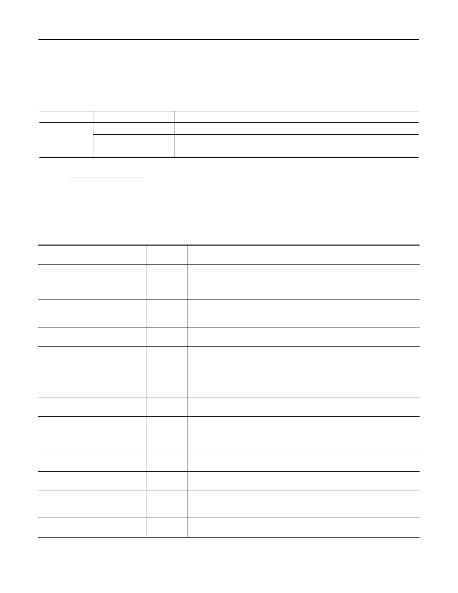
Display Item List
X: Applicable
System
Diagnosis mode
Description
METER/M&A
Self Diagnostic Result
The combination meter checks the conditions and displays memorized errors.
Data Monitor
Displays the combination meter input/output data in real time.
Warning History
Lighting history of the warning lamp and indicator lamp can be checked.
Display item [Unit]
MAIN
SIGNALS
Description
SPEED METER
[km/h]
X
Value of vehicle speed signal received from ABS actuator and electric unit (control
unit) via CAN communication.
NOTE:
655.35 is displayed when the malfunction signal is received.
SPEED OUTPUT
[km/h]
X
Vehicle speed signal value transmitted to other units via CAN communication.
NOTE:
655.35 is displayed when the malfunction signal is received.
ODO OUTPUT
[km/h or mph]
Odometer signal value transmitted to other units via CAN communication.
TACHO METER
[rpm]
X
• Value of the engine speed signal received from TCM via CAN communication
(CVT models).
• Value of the engine speed signal received from ECM via CAN communication
(M/T models).
NOTE:
8191.875 is displayed when the malfunction signal is received.
FUEL METER
[L]
X
Fuel level indicated on combination meter.
W TEMP METER
[
°C]
X
Value of engine coolant temperature signal is received from ECM via CAN com-
munication.
NOTE:
215 is displayed when the malfunction signal is input.
FUEL CAP W/L
[On/Off]
Status of fuel filler cap warning display detected from fuel filler cap warning display
signal received from ECM via CAN communication.
ABS W/L
[On/Off]
Status of ABS warning lamp detected from ABS warning lamp signal is received
from ABS actuator and electric unit (control unit) via CAN communication.
VDC/TCS IND
[On/Off]
Status of VDC OFF indicator lamp detected from VDC OFF indicator lamp signal
is received from ABS actuator and electric unit (control unit) via CAN communica-
tion.
SLIP IND
[On/Off]
Status of VDC warning lamp detected from VDC warning lamp signal received
from ABS actuator and electric unit (control unit) via CAN communication.