Nissan Juke F15. Manual - part 91
BR-24
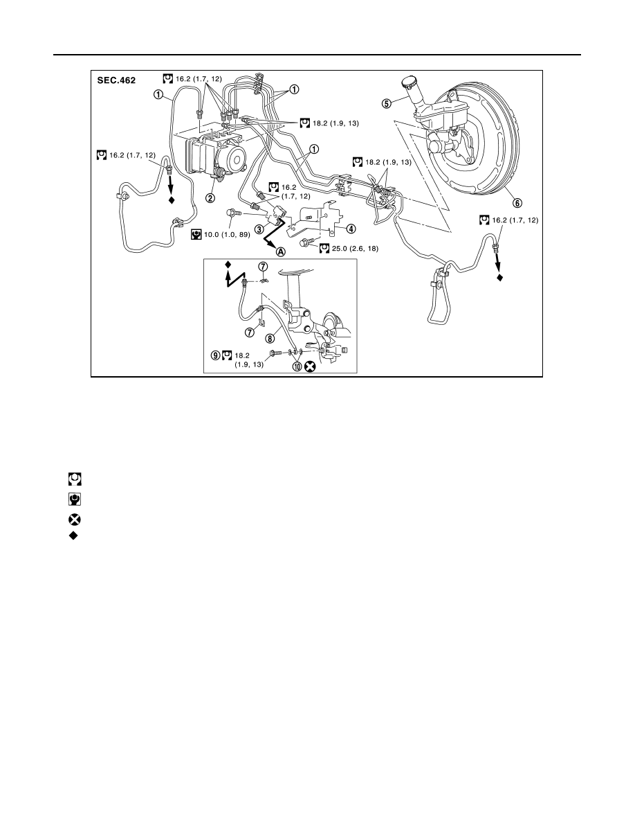
< REMOVAL AND INSTALLATION >
BRAKE PIPING
FRONT : Hydraulic Piping
INFOID:0000000012200280
2WD
1.
Brake tube
2.
ABS actuator and electric unit (con-
trol unit)
3.
Connector
4.
Connector bracket
5.
Master cylinder assembly
6.
Brake booster
7.
Lock plate
8.
Brake hose
9.
Union bolt
10. Copper washer
A.
To rear brake tube
: N·m (kg-m, ft-lb)
: N·m (kg-m, in-lb)
: Always replace after every disassembly.
: Indicates that the part is connected at points with same symbol in actual vehicle.
JSFIA0638GB