Nissan Juke F15. Manual - part 90
BR-20
< REMOVAL AND INSTALLATION >
BRAKE PEDAL
REMOVAL AND INSTALLATION
BRAKE PEDAL
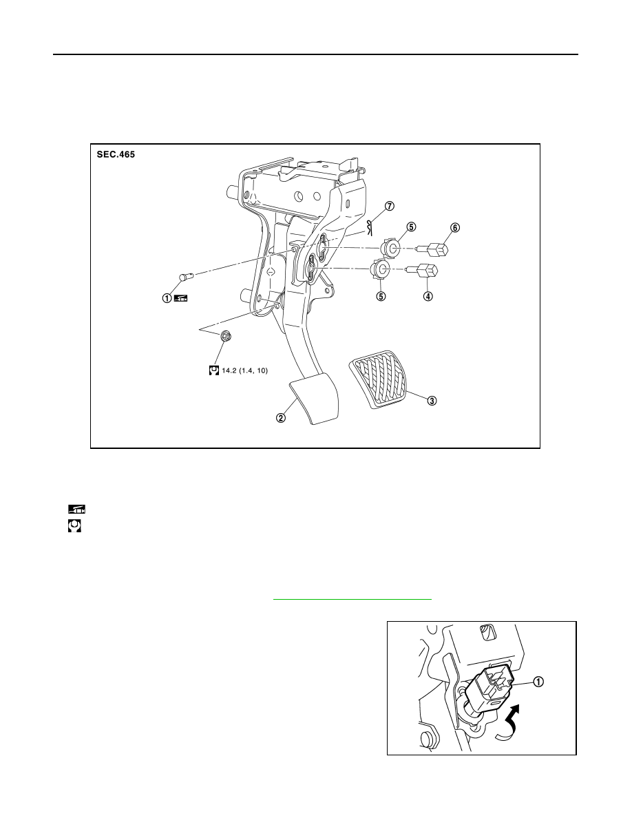
Exploded View
INFOID:0000000012200276
Removal and Installation
INFOID:0000000012200277
REMOVAL
1. Remove instrument lower panel. Refer to
IP-13, "Removal and Installation"
2. Disconnect the stop lamp switch and the brake pedal position switch harness connectors.
3. Rotate the stop lamp switch and the brake pedal position switch
(1) counter clockwise to remove.
4. Disconnect the accelerator pedal harness connector and har-
ness clip.
1.
Clevis pin
2.
Brake pedal assembly
3.
Brake pedal pad
4.
Brake pedal position switch
5.
Clip
6.
Stop lamp switch
7.
Snap pin
: Apply multi-purpose grease.
: N·m (kg-m, ft-lb)
JSFIA0457GB
JPFIA0815ZZ