Nissan Juke F15. Manual - part 38
AV-138
< DTC/CIRCUIT DIAGNOSIS >
[AUDIO WITH NAVIGATION]
U111C FRONT CAMERA IMAGE SIGNAL CIRCUIT
Is inspection result normal?
YES
>> GO TO 3.
NO
>> Replace around view monitor control unit. Refer to
AV-190, "Removal and Installation"
3.
CHECK CONTINUITY CAMERA IMAGE SIGNAL CIRCUIT
1. Turn ignition switch OFF.
2. Disconnect around view monitor control unit connector and front camera connector.
3. Check continuity between around view monitor control unit harness connector and front camera harness
connector.
4. Check continuity between around view monitor control unit harness connector and ground.
Is inspection result normal?
YES
>> GO TO 4.
NO
>> Repair harness or connector.
4.
CHECK CAMERA IMAGE SIGNAL
1. Connect around view monitor control unit connector and front camera connector.
2. Turn ignition switch ON.
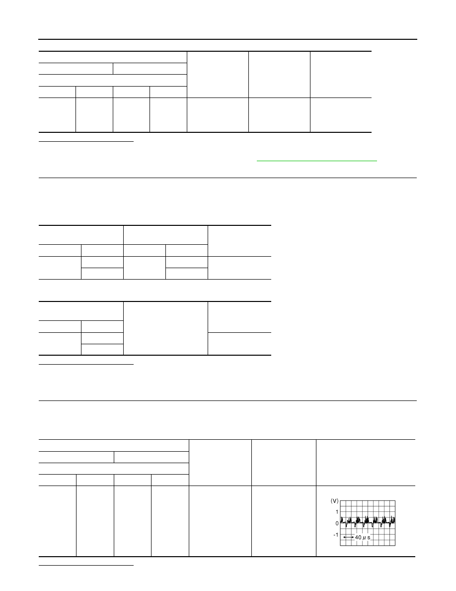
3. Check signal between around view monitor control unit harness connector terminals.
Is inspection result normal?
Terminal
Condition
Standard
Reference voltage
(Approx.)
(+)
(
−)
Around view monitor control unit
Connector
Terminal
Connector
Terminal
M98
6
M98
5
“CAMERA” switch
(around view moni-
tor switch) is ON or
shift position is “R”.
3.5 V or more
6.0 V
Around view monitor control
unit
Front camera
Continuity
Connector
Terminals
Connector
Terminals
M98
7
E72
4
Existed
8
3
Around view monitor control
unit
Ground
Continuity
Connector
Terminals
M98
7
Not existed
8
Terminal
Condition
Standard
Reference value
(+)
(
−)
Around view monitor control unit
Connector
Terminal
Connector
Terminal
M98
8
M98
7
Shift position is in
“R”.
Waveform accord-
ing to camera image
is input.
JSNIA0834GB