Nissan Juke F15. Manual - part 36
AV-130
< DTC/CIRCUIT DIAGNOSIS >
[AUDIO WITH NAVIGATION]
U1010 CONTROL UNIT (CAN)
U1010 CONTROL UNIT (CAN)
NAVI CONTROL UNIT
NAVI CONTROL UNIT : DTC Logic
INFOID:0000000012202535
DTC DETECTION LOGIC
AROUND VIEW MONITOR CONTROL UNIT
AROUND VIEW MONITOR CONTROL UNIT : Description
INFOID:0000000012202536
CAN controller controls the communication of CAN communication signal and the error detection.
AROUND VIEW MONITOR CONTROL UNIT : DTC Logic
INFOID:0000000012202537
DTC DETECTION LOGIC
AROUND VIEW MONITOR CONTROL UNIT : Diagnosis Procedure
INFOID:0000000012202538
1.
PERFORM DTC CONFIRMATION PROCEDURE
1. Start the engine.
2. Perform “All DTC Reading” with CONSULT.
3. Check if the “U1010” is detected as the current malfunction in “Self Diagnostic Result” of “AVM”.
Is “U1010” detected as the current malfunction?
YES
>> Replace the around view monitor control unit. Refer to
AV-190, "Removal and Installation"
NO
>> INSPECTION END
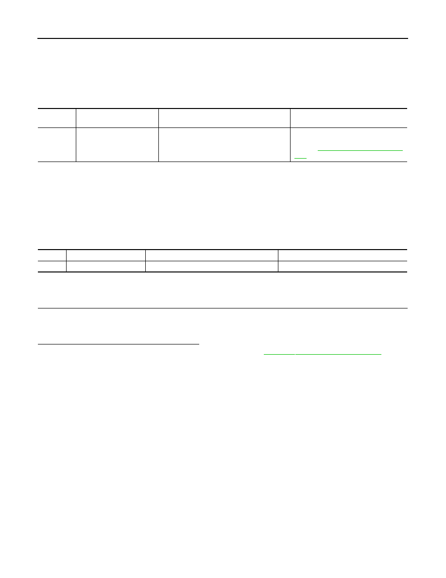
DTC No.
CONSULT screen terms
(Trouble diagnosis content)
DTC detection condition
Possible cause
U1010
CONTROL UNIT (CAN)
[Control unit (CAN)]
CAN initial diagnosis malfunction is detected.
Replace the NAVI control unit if the mal-
function occurs constantly.
Refer to
AV-182, "Removal and Installa-
DTC
Trouble diagnosis name
DTC detecting condition
Possible causes
U1010
CONTROL UNIT (CAN)
CAN initial diagnosis malfunction is detected.
Around view monitor control unit