Nissan Juke F15. Manual - part 33


  Index      Nissan     Nissan Juke F15 (2015 year) - Service and Repair Manual


Search            


Content   ..  31  32  33  34   ..


Nissan Juke F15. Manual - part 33


AV-118

< BASIC INSPECTION >

[AUDIO WITH NAVIGATION]

INSPECTION AND ADJUSTMENT

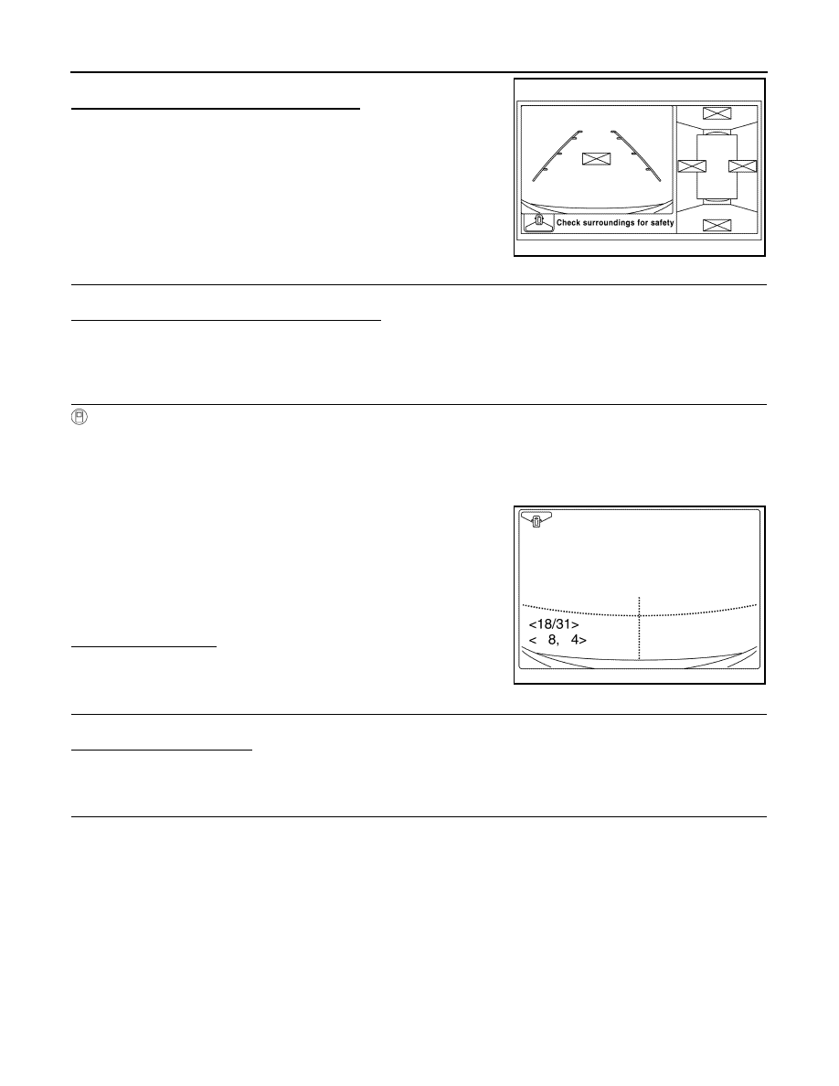
Check that there is no indication of “Incomplete calibration”.
Is the “Incomplete calibration” display visible?

YES

>> GO TO 2.

NO

>> GO TO 4.

2.

CHECK THAT AROUND VIEW MONITOR CONTROL UNIT IS REPLACED

Check that the around view monitor control unit is replaced.
Is the around view monitor control unit replaced?

YES

>> GO TO 3.

NO

>> GO TO 6.

3.

CANCEL THE INDICATION OF INCOMPLETE CALIBRATION (PERFORM THIS ONLY AFTER REPLAC-

ING AROUND VIEW MONITOR CONTROL UNIT.)

CONSULT work support

1. On the CONSULT screen, touch “CALIBRATING CAMERA IMAGE (FRONT CAMERA)”, “CALIBRATING

CAMERA IMAGE (PASS-SIDE CAMERA)”, “CALIBRATING CAMERA IMAGE (DR-SIDE CAMERA)”, or

“CALIBRATING CAMERA IMAGE (REAR CAMERA)” to accept the selection.

NOTE:

To cancel the indication of Incomplete calibration, select items based on the target camera. 

2. On the adjustment screen of each camera, touch “APPLY” but-

ton. After this, touch “OK” button.

CAUTION:

• Never perform operations other than those mentioned

above.

• Never perform “Initialize Camera Image Calibration”. 

3. Display the around view monitor screen to check that there is no

errors, such as deviations among the camera images.

Is there a malfunction?

YES

>> Calibration end

NO

>> GO TO 1.

4.

CHECK THAT ANY CAMERA IS REPLACED

Check that the any camera is replaced.
Is the any camera replaced?

YES

>> GO TO 6.

NO

>> GO TO 5.

5.

PERFORM SIMPLIFIED CONFIRMATION/ADJUSTMENT BY “FINE TUNING OF BIRDS-EYE VIEW”

1. Put target line 1 on the ground beside each axle using packing tape, etc. 

2. Put target lines 2 equal to the vehicle total length + approximately 1.0 m (39.3 in) from the vehicle side

(right and left) at approximately 30 cm (11.8 in) away from the vehicle (make the line as parallel with the

vehicle as possible) 

JSNIA4606ZZ

JSNIA4212ZZ

AV

INSPECTION AND ADJUSTMENT

AV-119

< BASIC INSPECTION >

[AUDIO WITH NAVIGATION]

C

D

E

F

G

H

I

J

K

L

M

B

A

O

P

Preparation of simplified target line

3.

CONSULT work support

Touch “FINE TUNING OF BIRDS-EYE VIEW” on the CONSULT screen.

4. On the CONSULT screen, touch “SELECT” button to select right or left camera and perform camera cali-

bration as instructed below:

-

If the marker on the screen deviates from Target line 1, touch “AXIS X” button and “AXIS Y” button to

adjust so that the marker is placed on the Target line 1.   

-

If Target line 2 is misaligned among the cameras, adjust each camera image to bring Target line 2 into a

straight line.

CAUTION:

Never adjust the front camera and rear camera. Only adjust the right and left cameras. 

Simplified target line adjustment method

5. Adjust right and left cameras. Touch "APPLY" on the CONSULT screen to display adjustment results. 

6. After adjusting right and left cameras, check that the marker is properly placed on the screen and there is

no deviation in Target line 1.    

NOTE:

• It can be initialized to the NISSAN factory default condition with “Initialize Camera Image Calibration”. 

• The adjustment value is cancelled on this mode by performing “Initialize Camera Image Calibration”. 

JSNIA0927ZZ

1.

Target lines 1

2.

Target lines 2

A.

Approx. 30 cm (11.8 in)

B.

Approx. 1.0 m (39.3 in)

JSNIA0929ZZ

1.

Target lines 1

2.

Target lines 2

3.

Marker for target line 1

4.

Boundary between cameras

5.

Crosshairs cursor (mark indicated 
the selected camera)

A.

Adjustment method for target lines 1 
(right)

B.

Adjustment method for target lines 2 
(right)

AV-120

< BASIC INSPECTION >

[AUDIO WITH NAVIGATION]

INSPECTION AND ADJUSTMENT

Is the difference corrected?

YES

>> On the CONSULT screen, touch “OK” button to complete writing to the around view monitor con-

trol unit.

NO

>> GO TO 6.

6.

PERFORM “CALIBRATING CAMERA IMAGE”

Preparation of target line

1. Hang a string with a weight as shown in the figure. Put the points FM0, RM0 (mark) on the ground at the

center of the vehicle front end and rear end with white packing tape or a pen. 

2. Route the vinyl string under the vehicle, and then pull and fix it on the point approximately 1.0 m (39.9 in)

to the front and rear of the vehicle through the points FM0 and RM0 using packing tape. 

Target line preparation procedure 1

3. Put the points FM and RM (mark) 75 cm (29.5 in) from the points FM0 and RM0 individually. 

4. Route the vinyl string through the points FM and RM using a triangle scale, and then fix it at approximately

1.5 m (59 in) on both sides with packing tape. 

5. Put the points FL, FR, RL, and RR (mark) to both right and left [vehicle width / 2 + 30 cm (11.8 in)] from the

points FM and RM. 

Target line preparation procedure 2

JSNIA4581ZZ

1.

Thread

2.

Weight

3.

Point FM0 (mark)

4.

Point RM0 (mark)

5.

Packing tape (to fix the vinyl string)

6.

Vinyl string

JSNIA0921ZZ

1.

Point FM

2.

Point RM

3.

Triangle scale

4.

Point FL (mark)

5.

Point FR (mark)

6.

Point RL (mark)

AV

INSPECTION AND ADJUSTMENT

AV-121

< BASIC INSPECTION >

[AUDIO WITH NAVIGATION]

C

D

E

F

G

H

I

J

K

L

M

B

A

O

P

6. Draw the lines of the points FL – RL and FR – RR with vinyl string, and fix it with packing tape. 

7. Put a mark on the center of each axle, draw vertical lines to the lines of the points FL – RL and FR – RR

from the marks on the center of the axle using a triangle scale, and then fix the lines using packing tape. 

Target line preparation procedure 3

Perform “Calibrating Camera Image”

CONSULT work support

1. On the CONSULT screen, touch “CALIBRATING CAMERA IMAGE (FRONT CAMERA)”, “CALIBRATING

CAMERA IMAGE (PASS-SIDE CAMERA)”, “CALIBRATING CAMERA IMAGE (DR-SIDE CAMERA)”, or

“CALIBRATING CAMERA IMAGE (REAR CAMERA)” to accept the selection.

NOTE:

To cancel the indication of Incomplete calibration, select items based on the target camera. 

2. On the adjustment screen of each camera, adjust the parameter

by touching the “AXIS X” button, “AXIS Y” button, and

“ROTATE” button to place the calibration marker shown on the

camera screen on the target line drawn on the ground.

3. Touch “APPLY” button on the CONSULT screen. “PRCSNG” is

displayed and adjustment results are shown on the camera screen.

CAUTION:

Check that “PRCSNG” is displayed. Do never perform other operations while “PRCSNG” is dis-

played. 

4. Touch “OK” button on the CONSULT screen. “PRCSNG” is displayed and adjustment results are written to

the around view monitor control unit.

CAUTION:

Check that “PRCSNG” is displayed. Do never perform other operations while “PRCSNG” is dis-

played. 

>> GO TO 7.

7.

PERFORM “FINE TUNING OF BIRDS-EYE VIEW”

7.

Point RR (mark)

A.

75 cm (29.5 in)

B.

Approx. 1.5 m (59 in)

C.

30 cm (11.8 in)
[Vehicle width/ 2 + 30 cm (11.8 in) 
from the points FM and RM]

JSNIA0922ZZ

1.

Point FL

2.

Point FR

3.

Point RL

4.

Point RR

5.

Center position of axle

6.

Triangle scale

Adjustment range
Rotation direction (Center dial)

: 31 patterns (16 on the center)

Upper/lower direction (upper/lower 
switch)

−22 – 22

Left/right direction (left/right switch)

−22 – 22

JSNIA4212ZZ


Content   ..  31  32  33  34   ..