Nissan Juke F15. Manual - part 25


  Index      Nissan     Nissan Juke F15 (2015 year) - Service and Repair Manual


Search            


Content   ..  23  24  25  26   ..


Nissan Juke F15. Manual - part 25


AV-86

< ECU DIAGNOSIS INFORMATION >

[AUDIO WITH NAVIGATION]

NAVI CONTROL UNIT

DTC Index

INFOID:0000000012202502
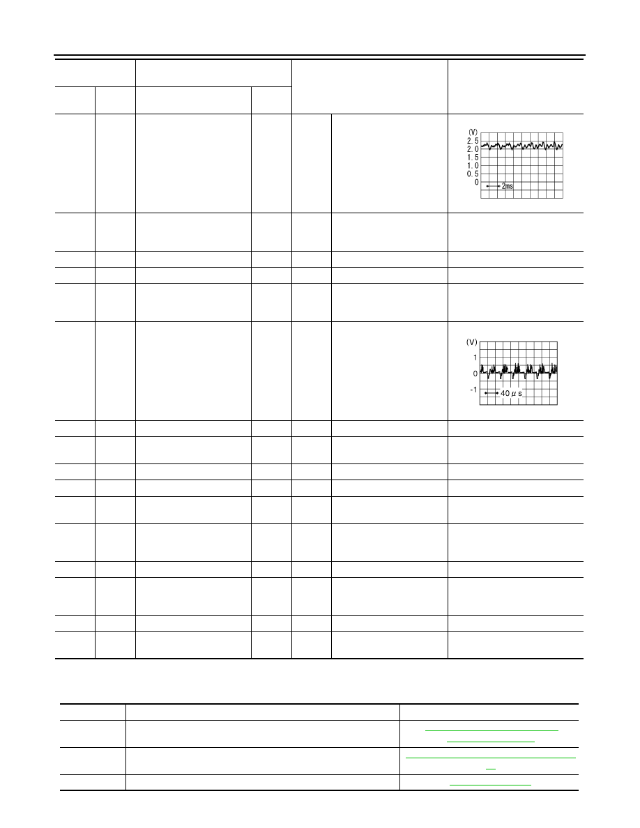
34

(W)

Ground Microphone signal

Input

Ignition 

switch 

ON

Give a voice.

35

(B)

Ground Microphone VCC

Output

Ignition 

switch 

ON

5.0 V

36

Shield

37

Shield

40

(LG)

Ground Ignition signal

Input

Ignition 

switch 

ON

12.0 V

41

(B)

Ground Camera image signal

Input

Ignition 

switch 

ON

When camera image is dis-
played.

42

Shield

45

V BUS signal

Input/

Output

46

USB D+ signal

Output

47

USB ground

49

USB D

− signal

Input/

Output

54

Ground GPS antenna signal

Input

Ignition 

switch 

ON

Not connected to GPS an-
tenna connector.

5.0 V

55

Shield

70

Ground Antenna amp. ON signal

Output

Ignition 

switch 

ACC

12.0 V

71

Antenna signal

Input

73

Satellite radio antenna sig-
nal

Input

Not connected to satellite 
antenna connector.

5.0 V

Terminal

(Wire color)

Description

Condition

Reference value

(Approx.)

+

Signal name

Input/

Output

PKIB5037J

JSNIA0834GB

DTC

Display item

Refer to

U1000

CAN COMM CIRC [U1000]

AV-128, "NAVI CONTROL UNIT : 

Diagnosis Procedure"

U1010

CONTROL UNIT (CAN) [U1010]

AV-130, "NAVI CONTROL UNIT : DTC Log-

ic"

U1200

Cont Unit [U1200]

AV-143, "DTC Logic"

AV

NAVI CONTROL UNIT

AV-87

< ECU DIAGNOSIS INFORMATION >

[AUDIO WITH NAVIGATION]

C

D

E

F

G

H

I

J

K

L

M

B

A

O

P

U1217

BLUETOOTH MODULE [U1217]

AV-144, "DTC Logic"

U1229

iPod CERTIFICATION [U1229]

AV-145, "DTC Logic"

U1244

GPS ANTENNA CONN [U1244]

AV-147, "Diagnosis Procedure"

U1258

SATELLITE RADIO ANTENNA [U1258]

AV-148, "Diagnosis Procedure"

U1263

USB OVERCURRENT [U1263]

AV-149, "Diagnosis Procedure"

U1264

ANTENNA AMP TERMINAL [U1264]

AV-150, "Diagnosis Procedure"

U12AA

CONFIGURATION ERROR [U12AA]

AV-151, "DTC Logic"

U12AB

FM ANTENNA ERROR [U12AB]

AV-152, "DTC Logic"

U12AC

DISPLAY TEMPERATURE TOO HIGH [U12AC]

AV-153, "DTC Logic"

U12AD

ECU TEMPERATURE TOO HIGH [U12AD]

AV-154, "DTC Logic"

U12AE

INTERNAL AMP TEMP WARNING [U12AE]

AV-155, "DTC Logic"

U12AF

CD MECHANISM TEMP WARNING [U12AF]

AV-156, "DTC Logic"

U12B0

SUPPLY VOLTAGE UNDER 9V [U12B0]

AV-157, "DTC Logic"

U12B1

SUPPLY VOLTAGE OVER 16V [U12B1]

AV-158, "DTC Logic"

DTC

Display item

Refer to

AV-88

< ECU DIAGNOSIS INFORMATION >

[AUDIO WITH NAVIGATION]

AROUND VIEW MONITOR CONTROL UNIT

AROUND VIEW MONITOR CONTROL UNIT

Reference Value

INFOID:0000000012202503

VALUES ON THE DIAGNOSIS TOOL

NOTE:

The following table includes information (items) inapplicable to this vehicle. For information (items) applicable

to this vehicle, refer to CONSULT display items.

CONSULT MONITOR ITEM

• *1: Once the signal is input, it remains ON indication until CONSULT is finished.

• *2: “Absolute” is always indicated on this vehicle.

• *3: “Type 0” is always indicated on this vehicle.

Monitor Item

Condition

Value/Status

ST ANGLE SENSOR SIGNAL

Ignition switch 
ON

Steering angle sensor signal is input condi-
tion.

ON

Except for above

OFF

REVERSE SIGNAL

Ignition switch 
ON

Shift position is in “R”

ON

Other than shift position is in “R”

OFF

VEHICLE SPEED SIGNAL

*1

Ignition switch 
ON

Vehicle speed signal is input condition.

ON

Except for above

OFF

CAMERA SWITCH SIGNAL

*1

Ignition switch 
ON

Pressing the “CAMERA” switch

ON

Except for above

OFF

CAMERA OFF SIGNAL

Ignition switch 
ON

While camera image is not indicated.

ON

While camera image is indicated.

OFF

ST ANGLE SENSOR TYPE

*2

Ignition switch 
ON

Absolute

STEERING GEAR RATIO TYPE

*3

Ignition switch 
ON

Type  0

STEERING POSITION

Ignition switch 
ON

LHD models

LHD

RHD models

RHD

REAR CAMERA IMAGE SIGNAL

Ignition switch 
ON

Input status of rear camera image signal is 
normal.

OK

Input status of rear camera image signal is 
not normal.

NG

F-CAMERA IMAGE SIGNAL

Ignition switch 
ON

Input status of front camera image signal is 
normal.

OK

Input status of front camera image signal is 
not normal.

NG

PA-SIDE CAMERA IMAGE SIG

Ignition switch 
ON

Input status of side camera RH image signal 
is normal. 

OK

Input status of side camera RH image signal 
is not normal. 

NG

DR-SIDE CAMERA IMAGE SIG

Ignition switch 
ON

Input status of side camera LH image signal 
is normal. 

OK

Input status of side camera LH image signal 
is not normal. 

NG

AV

AROUND VIEW MONITOR CONTROL UNIT

AV-89

< ECU DIAGNOSIS INFORMATION >

[AUDIO WITH NAVIGATION]

C

D

E

F

G

H

I

J

K

L

M

B

A

O

P

TERMINAL LAYOUT

PHYSICAL VALUES

JSNIA3987ZZ

Terminal

(Wire color)

Description

Condition

Standard

Reference value

(Approx.)

+

Signal name

Input/

Output

3

Shield

4

(B)

3

Camera image sig-
nal

Output

Igni-

tion 

switch 

ON

At camera image 
is displayed.

Waveform ac-
cording to cam-
era image is 
input.

5

(LG)

Ground

Front camera 
ground

Igni-

tion 

switch 

ON

0  V

6

(R)

5

(LG)

Front camera power 
supply

Output

Igni-

tion 

switch 

ON

“CAMERA” 
switch (around 
view monitor 
switch) is ON or 
shift position is 
“R”.

3.5 V or more

6.0 V

7

Shield

8

(V)

7

Front camera image 
signal

Input

Igni-

tion 

switch 

ON

“CAMERA” 
switch (around 
view monitor 
switch) is ON or 
shift position is 
“R”.

Waveform ac-
cording to cam-
era image is 
input.

9

(G)

Ground

Side camera pas-
senger side ground

Igni-

tion 

switch 

ON

0  V

10

(L)

9

(G)

Side camera pas-
senger side power 
supply

Output

Igni-

tion 

switch 

ON

“CAMERA” 
switch (around 
view monitor 
switch) is ON or 
shift position is 
“R”.

3.5 V or more

6.0 V

11

Shield

JSNIA0834GB

JSNIA0834GB


Content   ..  23  24  25  26   ..