Nissan Juke F15. Manual - part 5
AV-6
< PRECAUTION >
[DISPLAY AUDIO]
PRECAUTIONS
PRECAUTION
PRECAUTIONS
Precaution for Supplemental Restraint System (SRS) "AIR BAG" and "SEAT BELT
PRE-TENSIONER"
INFOID:0000000012202450
The Supplemental Restraint System such as “AIR BAG” and “SEAT BELT PRE-TENSIONER”, used along
with a front seat belt, helps to reduce the risk or severity of injury to the driver and front passenger for certain
types of collision. This system includes seat belt switch inputs and dual stage front air bag modules. The SRS
system uses the seat belt switches to determine the front air bag deployment, and may only deploy one front
air bag, depending on the severity of a collision and whether the front occupants are belted or unbelted.
Information necessary to service the system safely is included in the “SRS AIR BAG” and “SEAT BELT” of this
Service Manual.
WARNING:
Always observe the following items for preventing accidental activation.
• To avoid rendering the SRS inoperative, which could increase the risk of personal injury or death in
the event of a collision that would result in air bag inflation, it is recommended that all maintenance
and repair be performed by an authorized NISSAN/INFINITI dealer.
• Improper repair, including incorrect removal and installation of the SRS, can lead to personal injury
caused by unintentional activation of the system. For removal of Spiral Cable and Air Bag Module,
see “SRS AIR BAG”.
• Never use electrical test equipment on any circuit related to the SRS unless instructed to in this Ser-
vice Manual. SRS wiring harnesses can be identified by yellow and/or orange harnesses or harness
connectors.
PRECAUTIONS WHEN USING POWER TOOLS (AIR OR ELECTRIC) AND HAMMERS
WARNING:
Always observe the following items for preventing accidental activation.
• When working near the Air Bag Diagnosis Sensor Unit or other Air Bag System sensors with the
ignition ON or engine running, never use air or electric power tools or strike near the sensor(s) with
a hammer. Heavy vibration could activate the sensor(s) and deploy the air bag(s), possibly causing
serious injury.
• When using air or electric power tools or hammers, always switch the ignition OFF, disconnect the
battery or batteries, and wait at least 3 minutes before performing any service.
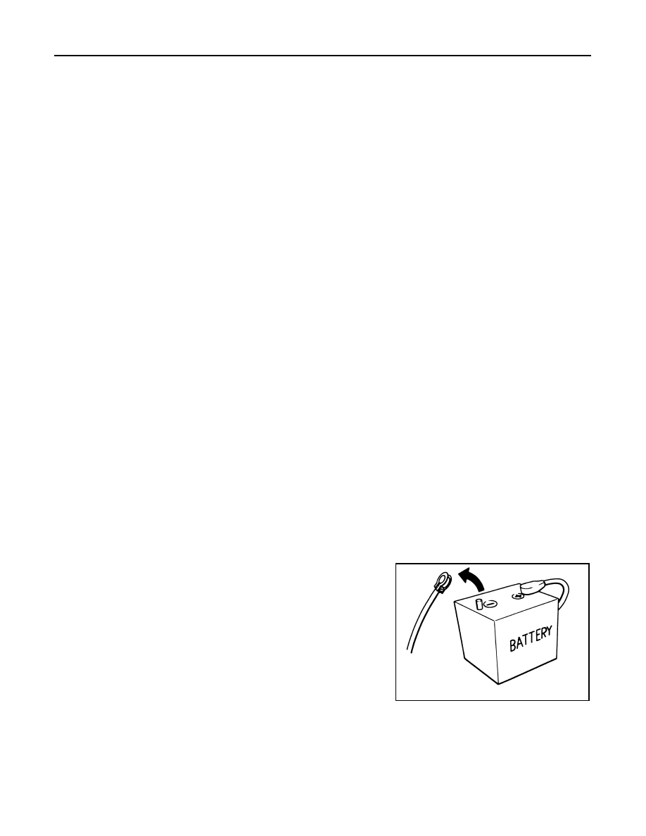
Precautions for Removing Battery Terminal
INFOID:0000000012947019
When disconnecting the battery terminal, pay attention to the following.
• Always use a 12V battery as power source.
• Never disconnect battery terminal while engine is running.
• When removing the 12V battery terminal, turn OFF the ignition
switch and wait at least 30 seconds.
• For vehicles with the engine listed below, remove the battery termi-
nal after a lapse of the specified time:
NOTE:
ECU may be active for several tens of seconds after the ignition switch is turned OFF. If the battery terminal
is removed before ECU stops, then a DTC detection error or ECU data corruption may occur.
• After high-load driving, if the vehicle is equipped with the V9X engine, turn the ignition switch OFF and wait
for at least 15 minutes to remove the battery terminal.
NOTE:
D4D engine
: 20 minutes
YS23DDT
: 4 minutes
HRA2DDT
: 12 minutes
YS23DDTT
: 4 minutes
K9K engine
: 4 minutes
ZD30DDTi
: 60 seconds
M9R engine
: 4 minutes
ZD30DDTT
: 60 seconds
R9M engine
: 4 minutes
V9X engine
: 4 minutes
YD25DDTi
: 2 minutes
SEF289H