содержание .. 755 756 757 758 ..
Nissan Tiida C11. Manual - part 757
EXL-26
< FUNCTION DIAGNOSIS >
DIAGNOSIS SYSTEM (BCM)
DIAGNOSIS SYSTEM (BCM)
COMMON ITEM
COMMON ITEM : CONSULT-III Function (BCM - COMMON ITEM)
INFOID:0000000001528970
APPLICATION ITEM
CONSULT-III performs the following functions via CAN communication with BCM.
BCM
BCM : CONSULT-III Function (BCM - BCM)
INFOID:0000000001528971
WORK SUPPORT
HEADLAMP
HEADLAMP : CONSULT-III Function (BCM - HEAD LAMP)
INFOID:0000000001528977
WORK SUPPORT
*: Initial setting
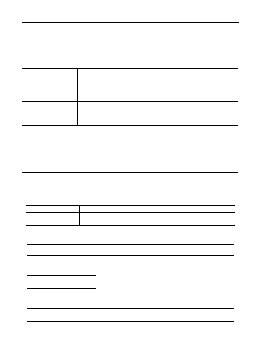
DATA MONITOR
Diagnosis mode
Function Description
WORK SUPPORT
Changes the setting for each system function.
SELF-DIAG RESULTS
Displays the diagnosis results judged by BCM. Refer to
CAN DIAG SUPPORT MNTR
Monitors the reception status of CAN communication viewed from BCM.
DATA MONITOR
The BCM input/output signals are displayed.
ACTIVE TEST
The signals used to activate each device are forcibly supplied from BCM.
ECU IDENTIFICATION
The BCM part number is displayed.
CONFIGURATION
• Enables to read and save the vehicle specification.
• Enables to write the vehicle specification when replacing BCM.
Item
Description
RESET SETTING VALUE
Return a value set with WORK SUPPORT of each system to a default value in factory shipment.
Work item
Setting
Description
BATTERY SAVER SET
ON*
Battery saver mode can be changed.
OFF
Monitor item
[Unit]
Description
IGN ON SW [ON/OFF]
Ignition switch (ON) status judged from IGN signal (ignition power supply)
HI BEAM SW [ON/OFF]
Each switch status that BCM judges from the combination switch reading function
H/L SW POS [ON/OFF]
LIGHT SW 1ST [ON/OFF]
PASSING SW [ON/OFF]
AUTO LIGHT SW [ON/OFF]
FR FOG SW [ON/OFF]
RR FOG SW [ON/OFF]
DOOR SW-DR [ON/OFF]
The switch status input from front door switch (driver side)
ENGINE STATUS
The engine status received from ECM with CAN communication