содержание .. 737 738 739 740 ..
Nissan Tiida C11. Manual - part 739
EM-308
< DISASSEMBLY AND ASSEMBLY >
[K9K]
CYLINDER HEAD
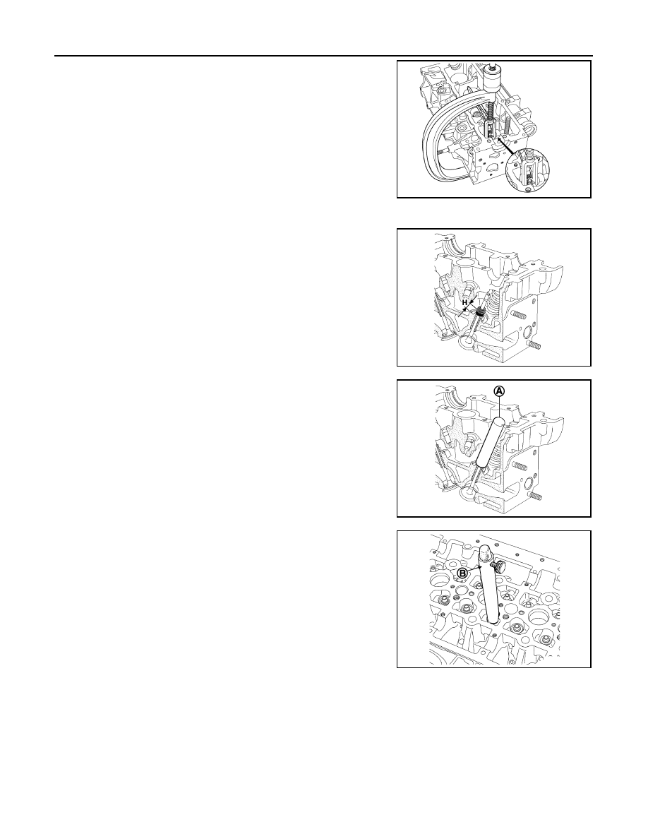
9.
Compress the valve springs using the valve lifter.
Remove the keys, upper cups and springs.
NOTE:
Before removing the valves and the valve stem seals, it is
vital to measure position “H” of one of the old seals in rela-
tion to the cylinder head using valve seal drift [KV113B0180
(Mot. 1511-01) (commercial service tool) or equivalent tool].
10. Install the push rod (A) of valve seal drift [KV113B0180 (Mot.
1511-01) (commercial service tool) or equivalent tool] on the
valve stem seal.
NOTE:
The inner diameter of the push rod must be identical to that
of the valve. In addition, the bottom of the push rod must
come into contact with the metal upper section of the valve
stem seal.
11. Install the guide tube (B) over the push rod until the guide tube
comes into contact with the cylinder head, locking the push rod
with the knurled wheel.
12. Remove the guide tube assembly plus push rod, being careful
not to loosen the knurled wheel.
13. Remove the valves and valve guide seals using the valve seal
remover [KV113B0090 (Mot. 1335) (commercial service tool) or
equivalent tool].
ASSEMBLY
MBIB0416E
MBIB0417E
MBIB0418E
MBIB0419E