содержание .. 738 739 740 741 ..
Nissan Tiida C11. Manual - part 740
EM-312
< DISASSEMBLY AND ASSEMBLY >
[K9K]
CYLINDER HEAD
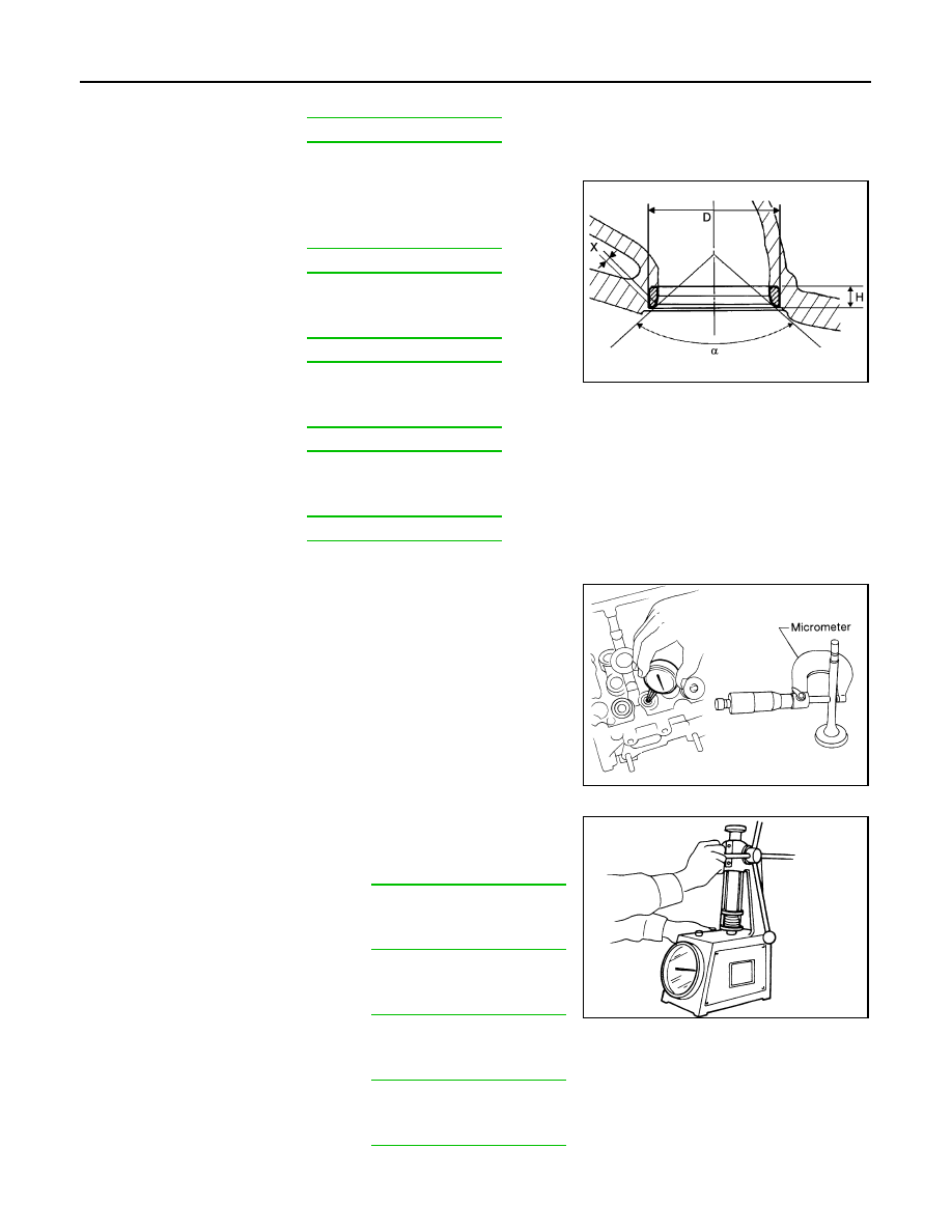
Valve Seat
Measure the valve seats as follows.
• Seat angle (
α
)
• Contacting width (X)
• Seat outer diameter (D):
• Cylinder head seat recess diameter (D)
Valve Guide Clearance
1.
Measure diameter of valve stem with micrometer.
2.
Measure inner diameter of valve guide with inside micrometer.
3.
Calculate the valve guide clearance.
(Valve guide clearance) = (Valve guide inner diameter) – (Valve
stem diameter)
• If it exceeds the limit, replace and/or valve guide.
Valve Spring
Measure the valve spring as follows.
• Free height
• Length under load
• Full pressed height
• Wire diameter
• Inner diameter
• Outer diameter
Intake
: Refer to
Exhaust
Intake
: Refer to
Exhaust
Intake
: Refer to
Exhaust
Intake
: Refer to
Exhaust
Intake
: Refer to
Exhaust
E1BIA0066ZZ
Intake
: 0.020 - 0.050 mm (0.0008 - 0.0020 in)
Exhaust
: 0.030 - 0.063 mm (0.0012 - 0.0025 in)
SEM938C
Intake and exhaust
: Refer to
Intake and exhaust
: Refer to
Intake and exhaust
: Refer to
Intake and exhaust
: Refer to
Intake and exhaust
: Refer to
SEM113