содержание .. 700 701 702 703 ..
Nissan Tiida C11. Manual - part 702
EM-160
< ON-VEHICLE REPAIR >
[MR18DE]
EXHAUST MANIFOLD
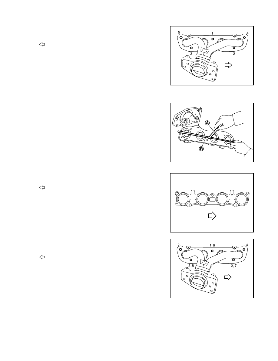
5.
Loosen nuts in reverse order as shown and remove exhaust
manifold.
CAUTION:
Cover engine openings to avoid entry of foreign materials.
INSPECTION AFTER REMOVAL
Surface Distortion
• Using straightedge (B) and feeler gauge (A), check the surface dis-
tortion of exhaust manifold mating surface in each exhaust port
and entire part.
• If it exceeds the limit, replace exhaust manifold.
INSTALLATION
1.
Install exhaust manifold gasket to cylinder head as shown.
2.
Tighten exhaust manifold nuts to specification in two stages in
the numerical order as shown.
: Engine front
PBIC3529J
Limit:
Each exhaust port
: 0.3 mm (0.012 in)
Entire part
: 0.7 mm (0.028 in)
PBIC3530J
: Engine front
PBIC3943E
: Engine front
WBIA0854E