Nissan Tiida C11. Manual - part 699


  Главная      Nissan     Nissan Tiida C11 - Service Manual


поиск по сайту            


содержание   ..  697  698  699  700   ..


Nissan Tiida C11. Manual - part 699


EM-148

< ON-VEHICLE MAINTENANCE >

[MR18DE]

CAMSHAFT VALVE CLEARANCE

CAMSHAFT VALVE CLEARANCE

Valve Clearance

INFOID:0000000001337799

INSPECTION

Perform inspection as follows after removal, installation or replacement of camshaft or valve-related parts, or if
there is unusual engine conditions regarding valve clearance. 

1.

Remove rocker cover. Refer to 

EM-173, "Removal and Installation"

.

2.

Measure the valve clearance with the following procedure:

a.

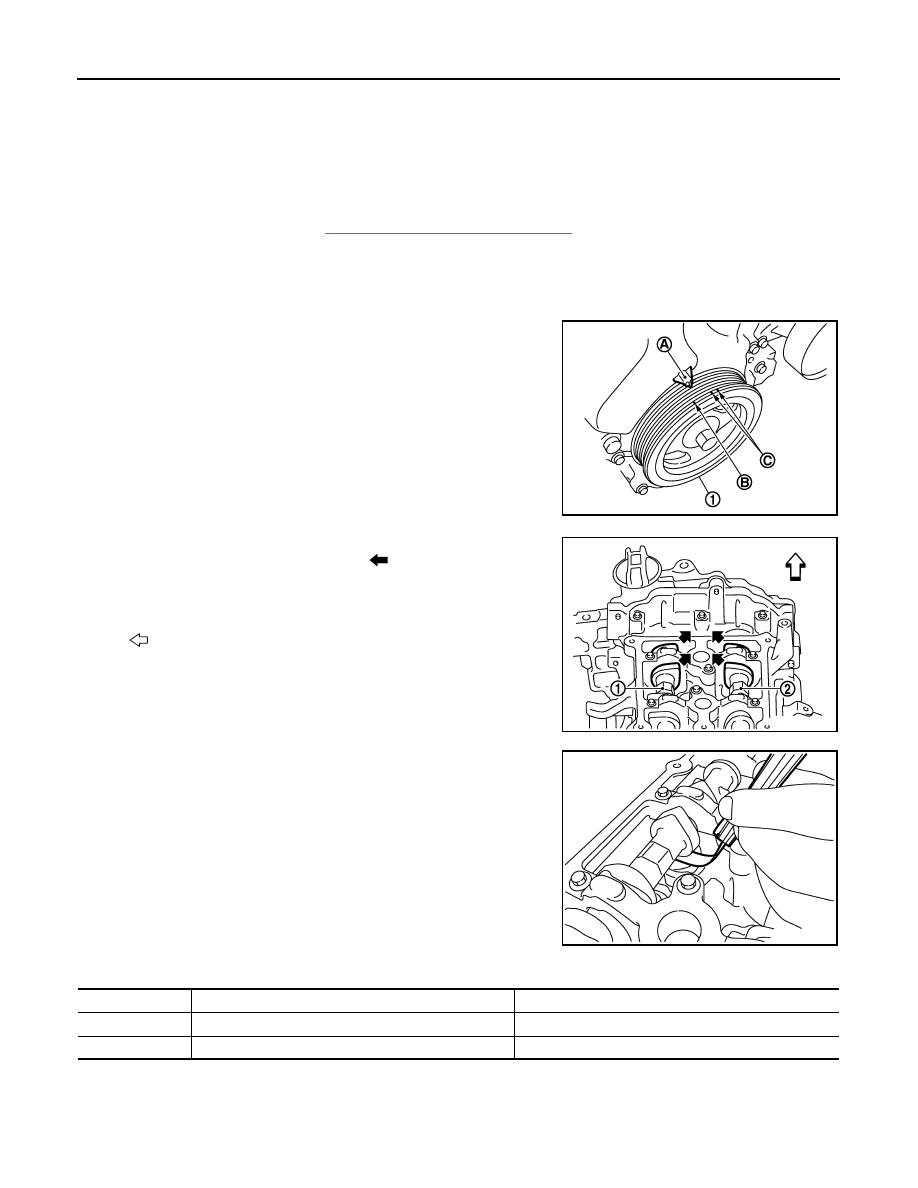
Set No. 1 cylinder at TDC of its compression stroke.
• Rotate crankshaft pulley (1) clockwise and align TDC mark (no paint) (B) to timing indicator (A) on front

cover.

• At the same time, make sure that both intake and exhaust cam

noses of No. 1 cylinder face inside (

) as shown.

• If they do not face inside, rotate crankshaft pulley once more

(360 degrees) and align as shown.

b.

Use a feeler gauge, measure the clearance between valve lifter
and camshaft. 

Valve clearance:

Unit: mm (in)

*: Approximately 80

°

C (176

°

F)

C : White paint mark (Not use for service)

PBIC3960E

1

: Camshaft (INT)

2

: Camshaft (EXH)

: Engine front

PBIC3359J

PBIC3192J

Cold

Hot * (reference data)

Intake

0.26 - 0.34 (0.010 - 0.013)

0.304 - 0.416 (0.012 - 0.016)

Exhaust

0.29 - 0.37 (0.011 - 0.015)

0.308 - 0.432 (0.012 - 0.017)

CAMSHAFT VALVE CLEARANCE

EM-149

< ON-VEHICLE MAINTENANCE >

[MR18DE]

C

D

E

F

G

H

I

J

K

L

M

A

EM

N

P

O

• By referring to the figure, measure the valve clearances at

locations marked “

×

” as shown in the table below [locations

indicated with black arrow (

)] with a feeler gauge.

• No. 1 cylinder compression TDC

c.

Set No.4 cylinder at TDC of its compression stroke.
• Rotate crankshaft pulley (1) one revolution (360 degrees) and

align TDC mark (no paint) (B) to timing indicator (A) on front
cover. 

• By referring to the figure, measure the valve clearance at loca-

tions marked “

×

” as shown in the table below [locations indi-

cated with black arrow (

)] with a feeler gauge. 

• No. 4 cylinder compression TDC

3.

If out of standard, perform adjustment procedure.

ADJUSTMENT

• Perform adjustment depending on selected head thickness of valve lifter.
1.

Remove camshaft. Refer to 

EM-186, "Removal and Installation"

.

2.

Remove valve lifters at the locations that are out of the standard.

Measuring position

No. 1 CYL.

No. 2 CYL.

No. 3 CYL.

No. 4 CYL.

No. 1 cylinder at 
compression TDC

EXH

×


×

INT

×


×


A

: Exhaust side

B

: No.1 cylinder

C

: No.2 cylinder

D

: No.3 cylinder

E

: No.4 cylinder

F

: Intake side

: Engine front

PBIC3193J

C : White paint mark (Not use for service)

PBIC3960E

Measuring position

No. 1 CYL.

No. 2 CYL.

No. 3 CYL.

No. 4 CYL.

No. 4 cylinder at 
compression TDC

EXH


×


×

INT


×


×

A

: Exhaust side

B

: No.1 cylinder

C

: No.2 cylinder

D

: No.3 cylinder

E

: No.4 cylinder

F

: Intake side

: Engine front

PBIC3194J

EM-150

< ON-VEHICLE MAINTENANCE >

[MR18DE]

CAMSHAFT VALVE CLEARANCE

3.

Measure the center thickness of the removed valve lifters with a
micrometer (A).

4.

Use the equation below to calculate valve lifter thickness for replacement.

• Thickness of new valve lifter (B) can be identified by stamp

mark (A) on the reverse side (inside the cylinder).
Stamp mark “302” indicates 3.02 mm (0.1189 in) in thickness.

NOTE:
Available thickness of valve lifter: 26 sizes range 3.00 to 3.50 mm (0.1181 to 0.1378 in) in steps of 0.02
mm (0.0008 in) (when manufactured at factory). Refer to 

EM-238, "Standard and Limit"

.

5.

Install the selected valve lifter.

6.

Install camshaft. Refer to 

EM-186, "Removal and Installation"

.

7.

Install timing chain and related parts. Refer to 

EM-176

.

8.

Manually rotate crankshaft pulley a few rotations. 

9.

Make sure that the valve clearances is within the standard. 

10. Installation of the remaining components is in the reverse order of removal.

PBIC3195J

Valve lifter thickness calculation:

t = t

1

   + (C

1

   – C

2

)

t

= Valve lifter thickness to be replaced

t

1


=  Removed  valve  lifter  thickness

C

1

= Measured valve clearance

C

2

= Standard valve clearance:

Intake

: 0.30 mm (0.012 in)

Exhaust

: 0.33 mm (0.013 in)

PBIC3196J

COMPRESSION PRESSURE

EM-151

< ON-VEHICLE MAINTENANCE >

[MR18DE]

C

D

E

F

G

H

I

J

K

L

M

A

EM

N

P

O

COMPRESSION PRESSURE

Checking Compression Pressure

INFOID:0000000001346452

1.

Warm up engine thoroughly. Then, stop it.

2.

Release fuel pressure. Refer to 

EC-1035, "Inspection"

.

3.

Disconnect fuel pump fuse (1) to avoid fuel injection during mea-
surement.

4.

Remove engine cover. Refer to 

EM-156, "Component"

.

5.

Remove ignition coil and spark plug from each cylinder. Refer to 

EM-145, "Removal and Installation"

.

6.

Connect an engine tachometer (not required in use of CONSULT-III).

7.

Install a suitable compression tester with an adapter onto spark
plug hole.

• Use the adapter whose picking up end inserted to spark plug

hole is smaller than 20 mm (0.79 in) in diameter. Otherwise, it
may be caught by cylinder head during removal.

8.

With accelerator pedal fully depressed, turn ignition switch to “START” for cranking. When the gauge
pointer stabilizes, read the compression pressure and the engine rpm. Perform these steps to check each
cylinder.

Compression pressure:

Unit: kPa (bar, kg/cm

2

  psi) /rpm

CAUTION:

Always use a fully charged battery to obtain the specified engine speed.
• If the engine speed is out of the specified range, check battery liquid for proper gravity. Check engine

speed again with normal battery gravity. 

: Vehicle front

PBIA9861J

LBIA0459E

SBIA0533E

Standard

Minimum

Differential limit between cylinders

 1,500 (15.0, 15.3, 217.6) / 200

 1,200 (12.0, 12.2, 174) / 200

     100 (1, 1, 15) / 200


содержание   ..  697  698  699  700   ..