Nissan Tiida C11. Manual - part 697


  Главная      Nissan     Nissan Tiida C11 - Service Manual


поиск по сайту            


содержание   ..  695  696  697  698   ..


Nissan Tiida C11. Manual - part 697


EM-140

< PREPARATION >

[MR18DE]

PREPARATION

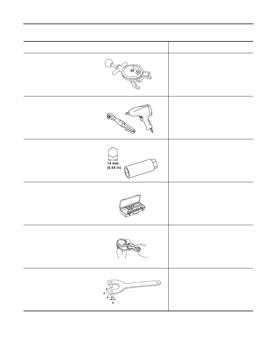
Commercial Service Tool

INFOID:0000000001337773

(Kent-Moore No.)
Tool name

Description

(BT-3373-F)
Belt tension gauge

Checking drive belt tension

Power tool

Loosening bolts and nuts

Spark plug wrench

Removing and installing spark plug

Valve seat cutter set

Finishing valve seat dimensions

Piston ring expander

Removing and installing piston ring

KV10109300
(

)

Pulley holder

Removing and installing crankshaft pulley

AMA126

PBIC0190E

PBIC2982E

NT048

NT030

NT628

PREPARATION

EM-141

< PREPARATION >

[MR18DE]

C

D

E

F

G

H

I

J

K

L

M

A

EM

N

P

O

KV10111800
Valve guide drift

Removing and installing valve guide

Valve guide reamer

(1): Reaming valve guide inner hole
(2): Reaming hole for oversize valve guide

(J-43897-18)
(J-43897-12)
Oxygen sensor thread cleaner

Reconditioning the exhaust system threads 
before installing a new oxygen sensor (Use 
with anti-seize lubricant shown below.)
a: J-43897-18 (18 mm dia.) for zirconia ox-
ygen sensor
b: J-43897-12 (12 mm dia.) for titania oxy-
gen sensor

Anti-seize lubricant (Permatex 133AR 
or equivalent meeting MIL specifica-
tion MIL-A-907)

Lubricating oxygen sensor thread cleaning 
tool when reconditioning exhaust system 
threads

E20 Torx® Socket
(J-45816)

Removing and installing drive plate and fly-
wheel bolts 

(Kent-Moore No.)
Tool name

Description

PBIC4012E

PBIC4013E

AEM488

AEM489

LBIA0285E

EM-142

< ON-VEHICLE MAINTENANCE >

[MR18DE]

DRIVE BELTS

ON-VEHICLE MAINTENANCE

DRIVE BELTS

Component

INFOID:0000000001337776

Checking Drive Belts

INFOID:0000000001337777

WARNING:

Be sure to perform this step when the engine is stopped.
• Make sure that the indicator (notch on fixed side) of drive belt auto-tensioner is within the possible use range

(A).
NOTE:
• Check the drive belt auto-tensioner indication when the engine is cold.
• When new drive belt is installed, the indicator (notch on fixed side) should be within the range (B).

• Visually check entire drive belt for wear, damage or cracks.
• If the indicator (notch on fixed side) is out of the possible use range or belt is damaged, replace drive belt.

Tension Adjustment

INFOID:0000000001337778

Belt tension is not necessary, as it is automatically adjusted by drive belt auto-tensioner.

Removal and Installation

INFOID:0000000001337779

REMOVAL

1.

Hold the hexagonal part (A) of drive belt auto-tensioner (1) with
a wrench securely. Then move the wrench handle in the direc-
tion of arrow (loosening direction of tensioner).

CAUTION:

Never place hand in a location where pinching may occur if
the holding tool accidentally comes off.

2.

Insert a rod such as short-length screwdriver approximately 6
mm (0.24 in) in diameter into the hole (B) of the retaining boss to
fix drive belt auto-tensioner.

3.

Remove drive belt. 

INSTALLATION

1.

Generator

2.

Drive belt auto–tensioner

3.

Crankshaft pulley

4.

A/C compressor (models with A/C)
Idler pulley (models without A/C)

5.

Water pump

6.

Drive belt

A.

Possible use range

B.

Range when new drive belt is installed C.

Indicator

PBIC3137J

PBIC3936E

DRIVE BELTS

EM-143

< ON-VEHICLE MAINTENANCE >

[MR18DE]

C

D

E

F

G

H

I

J

K

L

M

A

EM

N

P

O

1.

Hold the hexagonal part (A) of drive belt auto-tensioner (1) with
a box wrench securely. Then move the wrench handle in the
direction of arrow (loosening direction of tensioner).

CAUTION:

Never place hand in a location where pinching may occur if
the holding tool accidentally comes off.

2.

Insert a rod such as short-length screwdriver approximately 6
mm (0.24 in) in diameter into the hole (B) of retaining boss to fix
drive belt auto-tensioner.

3.

Install drive belt.

CAUTION:

• Confirm drive belt is completely set to pulleys.
• Check for engine oil, working fluid and engine coolant are not adhered to drive belt and each

pulley groove.

4.

Release drive belt auto-tensioner, and apply tension to drive belt.

5.

Turn crankshaft pulley clockwise several times to equalize tension between each pulley.

6.

Confirm tension of drive belt at indicator (notch on fixed side) is within the possible use range. Refer to

EM-142, "Checking Drive Belts"

.

PBIC3936E


содержание   ..  695  696  697  698   ..