содержание .. 670 671 672 673 ..
Nissan Tiida C11. Manual - part 672
EM-40
< ON-VEHICLE REPAIR >
[HR16DE]
OIL PAN (LOWER)
OIL PAN (LOWER)
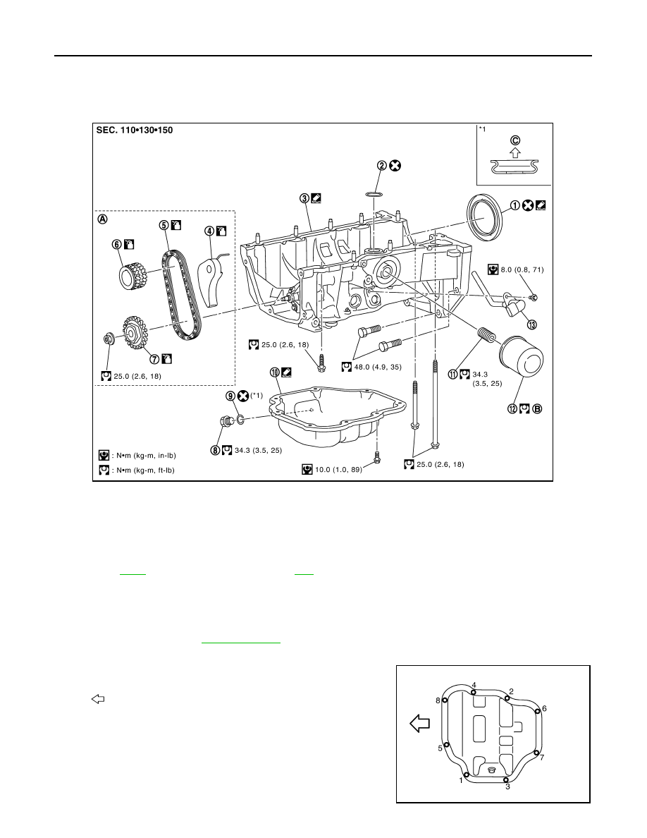
Exploded View
INFOID:0000000001381406
Removal and Installation
INFOID:0000000001381407
REMOVAL
1.
Drain engine oil. Refer to
.
2.
Remove the oil pan (lower) with the following procedure.
a.
Loosen bolts in the reverse of the order shown.
b.
Insert the seal cutter [SST: KV10111100] between oil pan
(upper) and oil pan (lower).
CAUTION:
• Be careful not to damage the mating surface.
• A more adhesive liquid gasket is applied compared to pre-
vious types when shipped, so it should not be forced off
using a flat- bladed screwdriver, etc.
1.
Rear oil seal
2.
O-ring
3.
Oil pan (upper)
4.
Chain tensioner
5.
Oil pump drive chain
6.
Crankshaft sprocket
7.
Oil pump sprocket
8.
Oil pan drain plug
9.
Washer
10.
Oil pan (lower)
11.
Oil filter stud bolt
12.
Oil filter
13.
Oil level sensor
A.
Refer to
B.
Refer to
C.
Oil pan side
JPBIA0553GB
: Engine front
PBIC4345E