содержание .. 668 669 670 671 ..
Nissan Tiida C11. Manual - part 670
EM-32
< ON-VEHICLE REPAIR >
[HR16DE]
EXHAUST MANIFOLD
EXHAUST MANIFOLD
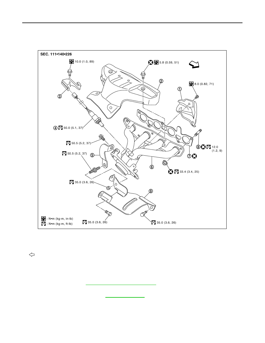
Exploded View
INFOID:0000000001381400
Removal and Installation
INFOID:0000000001381401
REMOVAL
1.
EXT-20, "Removal and Installation"
.
2.
Remove the engine room cover.
3.
Remove exhaust front tube. Refer to
.
4.
Remove the harness bracket of heated oxygen sensor 1 from the cylinder head.
5.
Remove exhaust manifold cover.
6.
Remove the heated oxygen sensor 1.
1.
Exhaust manifold cover
2.
Exhaust manifold cover
3.
Harness bracket
4.
Heated oxygen sensor 1
5.
Exhaust manifold stay
6.
Exhaust manifold
7.
Gasket
8.
Stud bolt
9.
Heat insulator
: Engine front
PBIC4750E