содержание .. 511 512 513 514 ..
Nissan Tiida C11. Manual - part 513
EC-702
< FUNCTION DIAGNOSIS >
[MR18DE]
ENGINE CONTROL SYSTEM
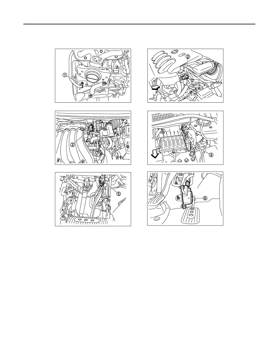
1.
Crankshaft position sensor (POS)
2.
Comshaft position sensor (PHASE)
3.
EVAP canistor purge volume control
solenoid valve
4.
ECM
5.
Stop lamp switch
6.
Accelerator pedal position sensor
PBIA9902J