содержание .. 487 488 489 490 ..
Nissan Tiida C11. Manual - part 489
EC-606
< COMPONENT DIAGNOSIS >
[HR16DE (WITHOUT EURO-OBD)]
FUEL PUMP
1.
Turn ignition switch OFF.
2.
Disconnect IDPDM E/R harness connector.
3.
Check the continuity between IPDM E/R harness connector and ECM harness connector.
Is the inspection result normal?
YES
>> GO TO 3.
NO
>> Repair open circuit or short to ground or short to power in harness or connectors.
3.
DETECT MALFUNCTIONING PART
Check the following.
• Harness or connectors E8, F8.
• Harness for open or short to ground and short power.
>> Repair harness or connectors.
4.
CHECK FUEL PUMP POWER SUPPLY CIRCUIT-III
1.
Turn ignition switch OFF.
2.
Reconnect all harness connectors disconnected.
3.
Disconnect “fuel level sensor unit and fuel pump” harness connector.
4.
Turn ignition switch ON.
5.
Check voltage between “fuel level sensor unit and fuel pump” harness connector and ground.
Is the inspection result normal?
YES
>> GO TO 8.
NO
>> GO TO 5.
5.
CHECK 10A FUSE
1.
Turn ignition switch OFF.
2.
Disconnect 15A fuse (No. 48) from IPDM E/R.
3.
Check 15A fuse.
Is the inspection result normal?
YES
>> GO TO 6.
NO
>> Replace fuse.
6.
CHECK FUEL PUMP POWER SUPPLY CIRCUIT-IV
1.
Disconnect IPDM E/R harness connector.
2.
Check the continuity between IPDM E/R harness connector and “fuel level sensor unit and fuel pump”
harness connector.
3.
Also check harness for short to ground and short to power.
Is the inspection result normal?
YES
>> GO TO 10.
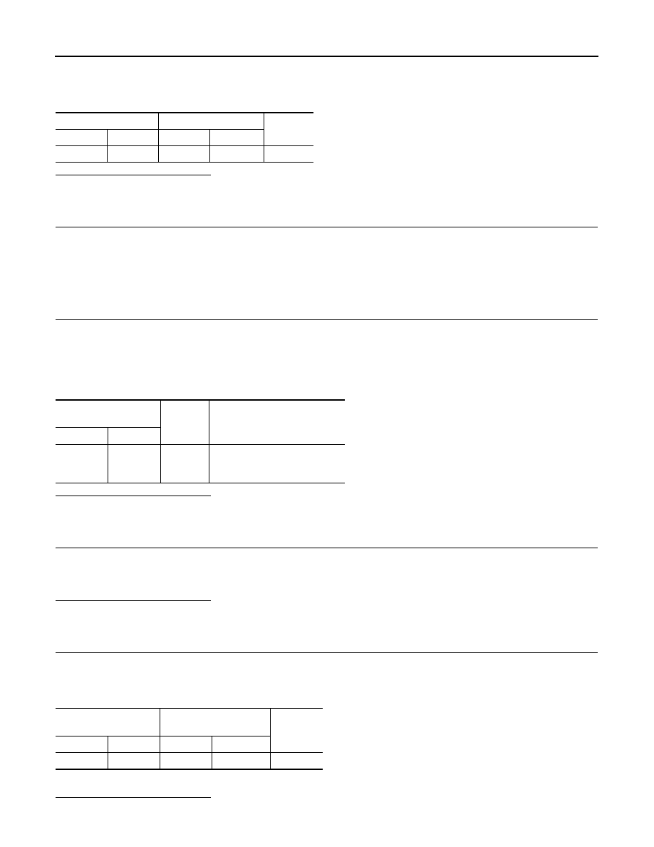
ECM
IPDM E/R
Continuity
Connector
Terminal
Connector
Terminal
F10
23
E46
47
Existed
Fuel level sensor unit
and fuel pump
Ground
Voltage
Connector
Terminal
B40
1
Ground
Battery voltage should exist 1
second after ignition switch is
turn ON.
IPDM E/R
Fuel level sensor unit and
fuel pump
Continuity
Connector
Terminal
Connector
Terminal
E45
36
B40
1
Existed