Nissan Tiida C11. Manual - part 488


  Главная      Nissan     Nissan Tiida C11 - Service Manual


поиск по сайту            


содержание   ..  486  487  488  489   ..


Nissan Tiida C11. Manual - part 488


EC-602

< COMPONENT DIAGNOSIS >

[HR16DE (WITHOUT EURO-OBD)]

FUEL INJECTOR

FUEL INJECTOR

Description

INFOID:0000000001693431

The fuel injector is a small, precise solenoid valve. When the ECM
supplies a ground to the fuel injector circuit, the coil in the fuel injec-
tor is energized. The energized coil pulls the ball valve back and
allows fuel to flow through the fuel injector into the intake manifold.
The amount of fuel injected depends upon the injection pulse dura-
tion. Pulse duration is the length of time the fuel injector remains
open. The ECM controls the injection pulse duration based on
engine fuel needs.

Component Function Check

INFOID:0000000001693432

1.

INSPECTION START

Turn ignition switch to START.
Is any cylinder ignited?

YES

>> GO TO 2.

NO

>> Go to 

EC-602, "Diagnosis Procedure"

.

2.

CHECK FUEL INJECTOR FUNCTION

With CONSULT-III

1.

Start engine.

2.

Perform “POWER BALANCE” in “ACTIVE TEST” mode with CONSULT-III.

3.

Make sure that each circuit produces a momentary engine speed drop.
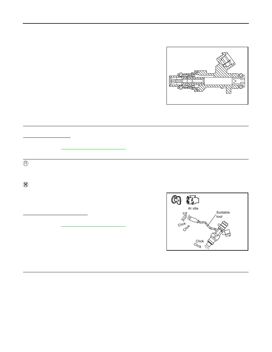
Without CONSULT-III

1.

Let engine idle.

2.

Listen to each fuel injector operating sound.

Is the inspection result normal?

YES

>> INSPECTION END

NO

>> Go to 

EC-602, "Diagnosis Procedure"

.

Diagnosis Procedure

INFOID:0000000001693433

1.

CHECK FUEL INJECTOR POWER SUPPLY CIRCUIT

1.

Turn ignition switch OFF.

2.

Disconnect fuel injector harness connector.

3.

Turn ignition switch ON.

4.

Check the voltage between fuel injector harness connector and ground.

PBIA9664J

Clicking noise should be heard.

PBIB3332E

FUEL INJECTOR

EC-603

< COMPONENT DIAGNOSIS >

[HR16DE (WITHOUT EURO-OBD)]

C

D

E

F

G

H

I

J

K

L

M

A

EC

N

P

O

Is the inspection result normal?

YES

>> GO TO 3.

NO

>> GO TO 2.

2.

DETECT MALFUNCTIONING PART

Check the following.
• Harness connectors F8, E8
• 10A fuse (No. 55)
• Harness for open or short between fuel injector and fuse

>> Repair open circuit or short to ground or short to power in harness or connectors.

3.

CHECK FUEL INJECTOR OUTPUT SIGNAL CIRCUIT FOR OPEN AND SHORT

1.

Turn ignition switch OFF.

2.

Disconnect ECM harness connector.

3.

Check the continuity between fuel injector harness connector and ECM harness connector.

4.

Also check harness for short to ground and short to power.

Is the inspection result normal?

YES

>> GO TO 4.

NO

>> Repair open circuit or short to ground or short to power in harness or connectors.

4.

CHECK FUEL INJECTOR

Refer to 

EC-603, "Component Inspection"

.

Is the inspection result normal?

YES

>> GO TO 5.

NO

>> Replace malfunctioning fuel injector.

5.

CHECK INTERMITTENT INCIDENT

Refer to 

GI-55, "Intermittent Incident"

.

>> INSPECTION END

Component Inspection

INFOID:0000000001693434

1.

CHECK FUEL INJECTOR

1.

Turn ignition switch OFF.

2.

Disconnect fuel injector harness connector.

3.

Check resistance between fuel injector terminals as follows.

Fuel injector

Ground

Voltage

Cylinder

Connector

Terminal

1

F17

1

Ground

Battery voltage

2

F18

1

3

F19

1

4

F20

1

Fuel injector

ECM

Continuity

Cylinder

Connector

Terminal

Connector

Terminal

1

F17

2

F10

31

Existed

2

F18

2

30

3

F19

2

29

4

F20

2

25

EC-604

< COMPONENT DIAGNOSIS >

[HR16DE (WITHOUT EURO-OBD)]

FUEL INJECTOR

Is the inspection result normal?

YES

>> INSPECTION END

NO

>> Replace malfunctioning fuel injector.

Terminals

Resistance [at 10 - 60

°

C (50 - 140

°

F)]

1 and 2

11.1 - 14.5

FUEL PUMP

EC-605

< COMPONENT DIAGNOSIS >

[HR16DE (WITHOUT EURO-OBD)]

C

D

E

F

G

H

I

J

K

L

M

A

EC

N

P

O

FUEL PUMP

Description

INFOID:0000000001693435

*: ECM determines the start signal status by the signals of engine speed and battery voltage.

The ECM activates the fuel pump for several seconds after the ignition switch is turned ON to improve engine
startability. If the ECM receives a engine speed signal from the camshaft position sensor (PHASE), it knows
that the engine is rotating, and causes the pump to operate. If the engine speed signal is not received when
the ignition switch is ON, the engine stalls. The ECM stops pump operation and prevents battery discharging,
thereby improving safety. The ECM does not directly drive the fuel pump. It controls the ON/OFF fuel pump
relay, which in turn controls the fuel pump.

Component Function Check

INFOID:0000000001693436

1.

CHECK FUEL PUMP FUNCTION

1.

Turn ignition switch ON.

2.

Pinch fuel feed hose with two fingers.

Is the inspection result normal?

YES

>> INSPECTION END

NO

>>

EC-605, "Diagnosis Procedure"

.

Diagnosis Procedure

INFOID:0000000001693437

1.

CHECK FUEL PUMP POWER SUPPLY CIRCUIT-I

1.

Turn ignition switch OFF.

2.

Disconnect ECM harness connector.

3.

Turn ignition switch ON.

4.

Check the voltage between ECM harness connector terminals as follows.

Is the inspection result normal?

YES

>> GO TO 4.

NO

>> GO TO 2.

2.

CHECK FUEL PUMP POWER SUPPLY CIRCUIT-II

Sensor

Input signal to ECM

ECM Function

Actuator

Crankshaft position sensor (POS)
Camshaft position sensor (PHASE)

Engine speed*

Fuel pump control

Fuel pump relay

Fuel pump

Battery

Battery voltage*

Condition

Fuel pump operation

Ignition switch is turned to ON.

Operates for 1 second.

Engine running and cranking

Operates.

When engine is stopped

Stops in 1.5 seconds.

Except as shown above

Stops.

Fuel pressure pulsation should be felt on the fuel feed 
hose for 1 second after ignition switch is turned ON.

ALBIA0276ZZ

(+)

(–)

Voltage

Connector

Terminal

Connector

Terminal

F10

23

E16

108

Battery voltage


содержание   ..  486  487  488  489   ..