содержание .. 418 419 420 421 ..
Nissan Tiida C11. Manual - part 420
EC-330
< ECU DIAGNOSIS >
[HR16DE (WITH EURO-OBD)]
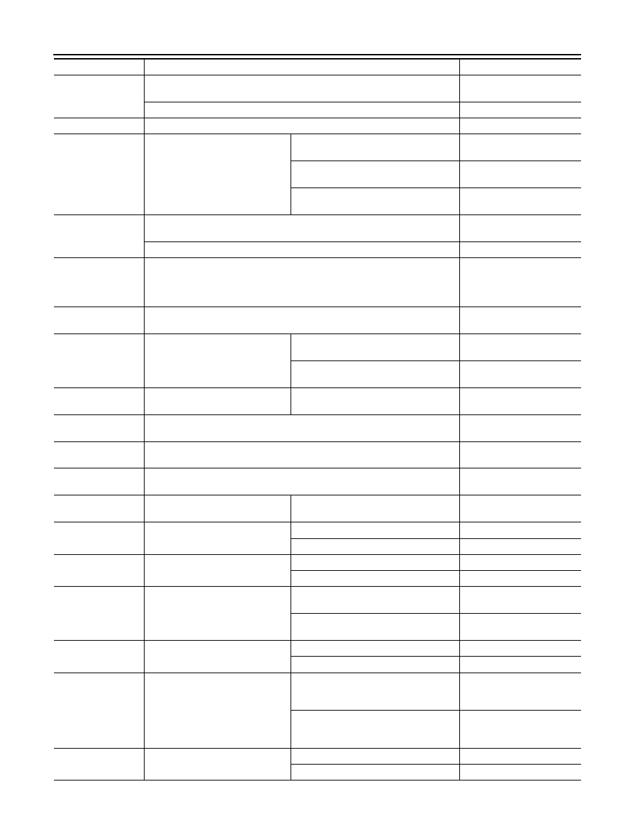
ECM
FUEL PUMP RLY
• For 1 seconds after turning ignition switch: ON
• Engine running or cranking
ON
• Except above
OFF
THRTL RELAY
• Ignition switch: ON
ON
COOLING FAN
• Engine: After warning up, idle the
engine
• Air conditioner switch: OFF
Engine coolant temperature is 98
°
C
(208
°
F) or less
OFF
Engine coolant temperature is between
98
°
C (208
°
F) and 99
°
C (210
°
F)
LOW
Engine coolant temperature is 100
°
C
(212
°
F) or more
HIGH
HO2S1 HTR (B1)
• Engine: After warming up
• Engine speed: Below 3,600rpm
ON
• Engine speed: Above 3,600 rpm
OFF
HO2S2 HTR (B1)
• Engine speed: Below 3,900 rpm after the following conditions are met.
- Engine: After warming up
- Keeping the engine speed between 3,500 and 4,000 rpm for 1 minute and at
idle for 1 minute under no load
ON
VEHICLE SPEED
• Turn drive wheels and compare CONSULT-III value with the speedometer in-
dication.
Almost the same speed as
the speedometer indication
IDL A/V LEARN
• Engine: running
Idle air volume learning has not been per-
formed yet.
YET
Idle air volume learning has already been
performed successfully.
CMPLT
TRVL AFTER MIL
• Ignition switch: ON
Vehicle has traveled after MI has turned
ON.
0 - 65,535 km
(0 - 40,723 miles)
O2 SEN HTR DTY
• Engine coolant temperature when engine started: More than 80
°
C (176F)
• Engine speed: Below 3,600 rpm
Approx. 30%
AC PRESS SEN
• Engine: Idle
• Both A/C switch and blower fan switch: ON (Compressor operates)
1.0 - 4.0V
VHCL SPEED SE
• Turn drive wheels and compare CONSULT-III value with the speedometer in-
dication.
Almost the same speed as
the speedometer indication
SET VHCL SPD
• Engine: Running
ASCD: Operating
The preset vehicle speed is
displayed
MAIN SW
• Ignition switch: ON
MAIN switch: Pressed
ON
MAIN switch: Released
OFF
CANCEL SW
• Ignition switch: ON
CANCEL switch: Pressed
ON
CANCEL switch: Released
OFF
RESUME/ACC SW
• Ignition switch: ON
RESUME/ACCELERATE switch:
Pressed
ON
RESUME/ACCELERATE switch: Re-
leased
OFF
SET SW
• Ignition switch: ON
SET/COAST switch: Pressed
ON
SET/COAST switch: Released
OFF
BRAKE SW1
(ASCD brake switch)
• Ignition switch: ON
• Brake pedal: Fully released (A/T)
• Brake pedal and clutch pedal: Fully re-
leased (M/T)
ON
• Brake pedal: Slightly depressed (A/T)
• Brake pedal and/or clutch pedal: Slight-
ly depressed (M/T)
OFF
BRAKE SW2
(Stop lamp switch)
• Ignition switch: ON
Brake pedal: Fully released
OFF
Brake pedal: Slightly depressed
ON
Monitor Item
Condition
Values/Status