содержание .. 417 418 419 420 ..
Nissan Tiida C11. Manual - part 419
EC-326
< COMPONENT DIAGNOSIS >
[HR16DE (WITH EURO-OBD)]
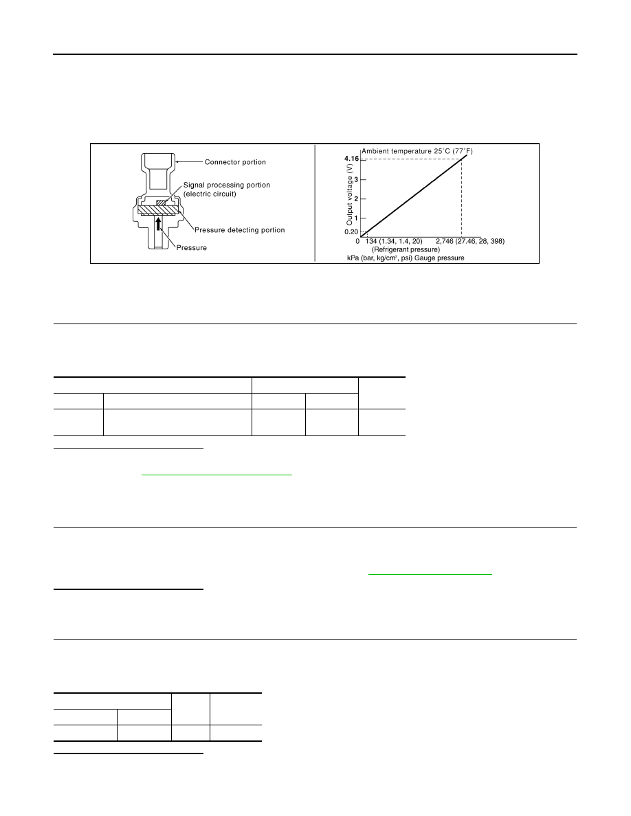
REFRIGERANT PRESSURE SENSOR
REFRIGERANT PRESSURE SENSOR
Description
INFOID:0000000001671117
The refrigerant pressure sensor is installed at the condenser of the air conditioner system. The sensor uses an
electrostatic volume pressure transducer to convert refrigerant pressure to voltage. The voltage signal is sent
to ECM, and ECM controls cooling fan system.
Component Function Check
INFOID:0000000001671118
1.
CHECK REFRIGERANT PRESSURE SENSOR OVERALL FUNCTION
1.
Start engine and warm it up to normal operating temperature.
2.
Turn A/C switch and blower fan switch ON.
3.
Check the voltage between ECM harness connector terminals as follows.
Is the inspection result normal?
YES
>> INSPECTION END
NO
>> Go to
Diagnosis Procedure
INFOID:0000000001671119
1.
CHECK GROUND CONNECTION
1.
Turn A/C switch and blower fan switch OFF.
2.
Stop engine.
3.
Turn ignition switch OFF.
4.
Check ground connection E15. Refer to Ground Inspection in
.
Is the inspection result normal?
YES
>> GO TO 2.
NO
>> Repair or replace ground connection.
2.
CHECK REFRIGERANT PRESSURE SENSOR POWER SUPPLY CIRCUIT
1.
Disconnect refrigerant pressure sensor harness connector.
2.
Turn ignition switch ON.
3.
Check the voltage between refrigerant pressure sensor harness connector and ground.
Is the inspection result normal?
YES
>> GO TO 4.
NO
>> GO TO 3.
PBIB2657E
(+)
(–)
Voltage
Connector
Terminal
Connector
Terminal
F11
41
(Refrigerant pressure sensor signal)
F11
48
1.0 - 4.0V
Refrigerant pressure sensor
Ground
Voltage
Connector
Terminal
E17
3
Ground
Approx. 5V