Nissan Tiida C11. Manual - part 418


  Главная      Nissan     Nissan Tiida C11 - Service Manual


поиск по сайту            


содержание   ..  416  417  418  419   ..


Nissan Tiida C11. Manual - part 418


EC-322

< COMPONENT DIAGNOSIS >

[HR16DE (WITH EURO-OBD)]

IGNITION SIGNAL

Component Inspection (Ignition Coil with Power Transistor)

INFOID:0000000001671110

1.

CHECK IGNITION COIL WITH POWER TRANSISTOR-I

1.

Turn ignition switch OFF.

2.

Disconnect ignition coil harness connector.

3.

Check resistance between ignition coil terminals as follows.

Is the inspection result normal?

YES

>> GO TO 2.

NO

>> Replace malfunctioning ignition coil with power transistor.

2.

CHECK IGNITION COIL WITH POWER TRANSISTOR-II

CAUTION:

Do the following procedure in the place where ventilation is good without the combustible.
1.

Turn ignition switch OFF.

2.

Reconnect all harness connectors disconnected.

3.

Remove fuel pump fuse in IPDM E/R to release fuel pressure.
NOTE:
Do not use CONSULT-III to release fuel pressure, or fuel pressure applies again during the following pro-
cedure.

4.

Start engine.

5.

After engine stalls, crank it two or three times to release all fuel pressure.

6.

Turn ignition switch OFF.

7.

Remove all ignition coil harness connectors to avoid the electrical discharge from the ignition coils.

8.

Remove ignition coil and spark plug of the cylinder to be checked.

9.

Crank engine for 5 seconds or more to remove combustion gas in the cylinder.

10. Connect spark plug and harness connector to ignition coil.
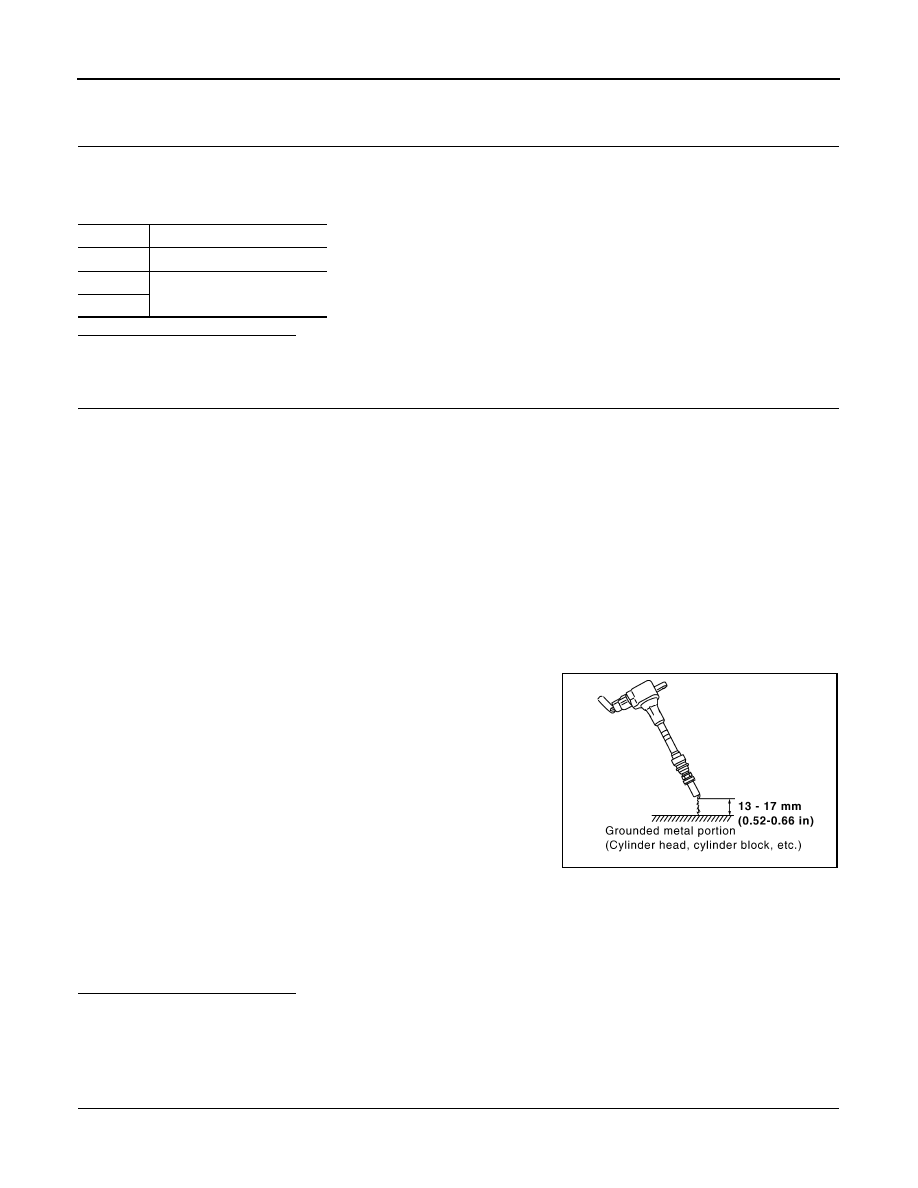
11. Fix ignition coil using a rope etc. with gap of 13 - 17 mm (0.52 -

0.66 in) between the edge of the spark plug and grounded metal
portion as shown in the figure.

12. Crank engine for about three seconds, and check whether spark

is generated between the spark plug and the grounded metal
portion.

CAUTION:

• Do not approach to the spark plug and the ignition coil

within 50 cm (19.7 in). Be careful not to get an electrical
shock while checking, because the electrical discharge
voltage becomes 20kV or more.

• It might cause to damage the ignition coil if the gap of more than 17 mm 0.66 in) is taken.
NOTE:
When the gap is less than 13 mm (0.52 in), the spark might be generated even if the coil is mal-
functioning.

Is the inspection result normal?

YES

>> INSPECTION END

NO

>> Replace malfunctioning ignition coil with power transistor.

Component Inspection (Condenser)

INFOID:0000000001671111

1.

CHECK CONDENSER

1.

Turn ignition switch OFF.

2.

Disconnect condenser-2 harness connector.

Terminals

Resistance [at 25

°

C (77

°

F)]

1 and 2

Except 0 or 


1 and 3

Except 0 

2 and 3

Spark should be generated.

JMBIA0066GB

IGNITION SIGNAL

EC-323

< COMPONENT DIAGNOSIS >

[HR16DE (WITH EURO-OBD)]

C

D

E

F

G

H

I

J

K

L

M

A

EC

N

P

O

3.

Check resistance between condenser-2 terminals as follows.

Is the inspection result normal?

YES

>> INSPECTION END

NO

>> Replace condenser.

Terminals

Resistance

1 and 2

Above 1 M

 [at 25

°

C (77

°

F)]

EC-324

< COMPONENT DIAGNOSIS >

[HR16DE (WITH EURO-OBD)]

MALFUNCTION INDICATOR

MALFUNCTION INDICATOR

Description

INFOID:0000000001671112

The Malfunction Indicator  (MI) is located on the combination meter.
The MI will light up when the ignition switch is turned ON without the
engine running. This is a bulb check.
When the engine is started, the MI should go off. If the MI remains
on, the on board diagnostic system has detected an engine system
malfunction.
For details, refer to 

EC-324, "Diagnosis Procedure"

.

Component Function Check

INFOID:0000000001671113

1.

CHECK MI FUNCTION

1.

Turn ignition switch ON.

2.

Make sure that MI lights up.

Is the inspection result normal?

YES

>> INSPECTION END

NO

>> Go to 

EC-324, "Diagnosis Procedure"

.

Diagnosis Procedure

INFOID:0000000001671114

1.

CHECK DTC

Check that DTC U1000 or U1001 is not displayed.

Is the inspection result normal?

YES

>> GO TO 2.

NO

>> Perform trouble diagnosis for DTC U1000, U1001. Refer to 

EC-128, "Diagnosis Procedure"

.

2.

CHECK DTC WITH COMBINATION METER

Refer to 

MWI-22, "CONSULT-III Function (METER/M&A)"

.

Is the inspection result normal?

YES

>> GO TO 3.

NO

>> Repair or replace.

3.

CHECK INTERMITTENT INCIDENT

Refer to 

GI-55, "Intermittent Incident"

.

Is the inspection result normal?

YES

>> Replace combination meter.

NO

>> Repair or replace.

SAT652J

POSITIVE CRANKCASE VENTILATION

EC-325

< COMPONENT DIAGNOSIS >

[HR16DE (WITH EURO-OBD)]

C

D

E

F

G

H

I

J

K

L

M

A

EC

N

P

O

POSITIVE CRANKCASE VENTILATION

Description

INFOID:0000000001671115

This system returns blow-by gas to the intake manifold.
The positive crankcase ventilation (PCV) valve is provided to conduct crankcase blow-by gas to the intake
manifold.
During partial throttle operation of the engine, the intake manifold sucks the blow-by gas through the PCV
valve.
Normally, the capacity of the valve is sufficient to handle any blow-by and a small amount of ventilating air.
The ventilating air is then drawn from the air inlet tubes into the crankcase. In this process the air passes
through the hose connecting air inlet tubes to rocker cover.
Under full-throttle condition, the manifold vacuum is insufficient to draw the blow-by flow through the valve.
The flow goes through the hose connection in the reverse direction.
On vehicles with an excessively high blow-by, the valve does not
meet the requirement. This is because some of the flow will go
through the hose connection to the air inlet tubes under all condi-
tions.

Component Inspection

INFOID:0000000001671116

1.

CHECK PCV VALVE

With engine running at idle, remove PCV valve from rocker cover. A
properly working valve makes a hissing noise as air passes through
it. A strong vacuum should be felt immediately when a finger is
placed over valve inlet.

Is the inspection result normal?

YES

>> INSPECTION END

NO

>> Replace PCV valve.

PBIB0492E

PBIB1588E

PBIB1589E


содержание   ..  416  417  418  419   ..