содержание .. 330 331 332 333 ..
Nissan Tiida C11. Manual - part 332
DLK-738
< REMOVAL AND INSTALLATION >
[WITHOUT I-KEY, WITH SUPER LOCK]
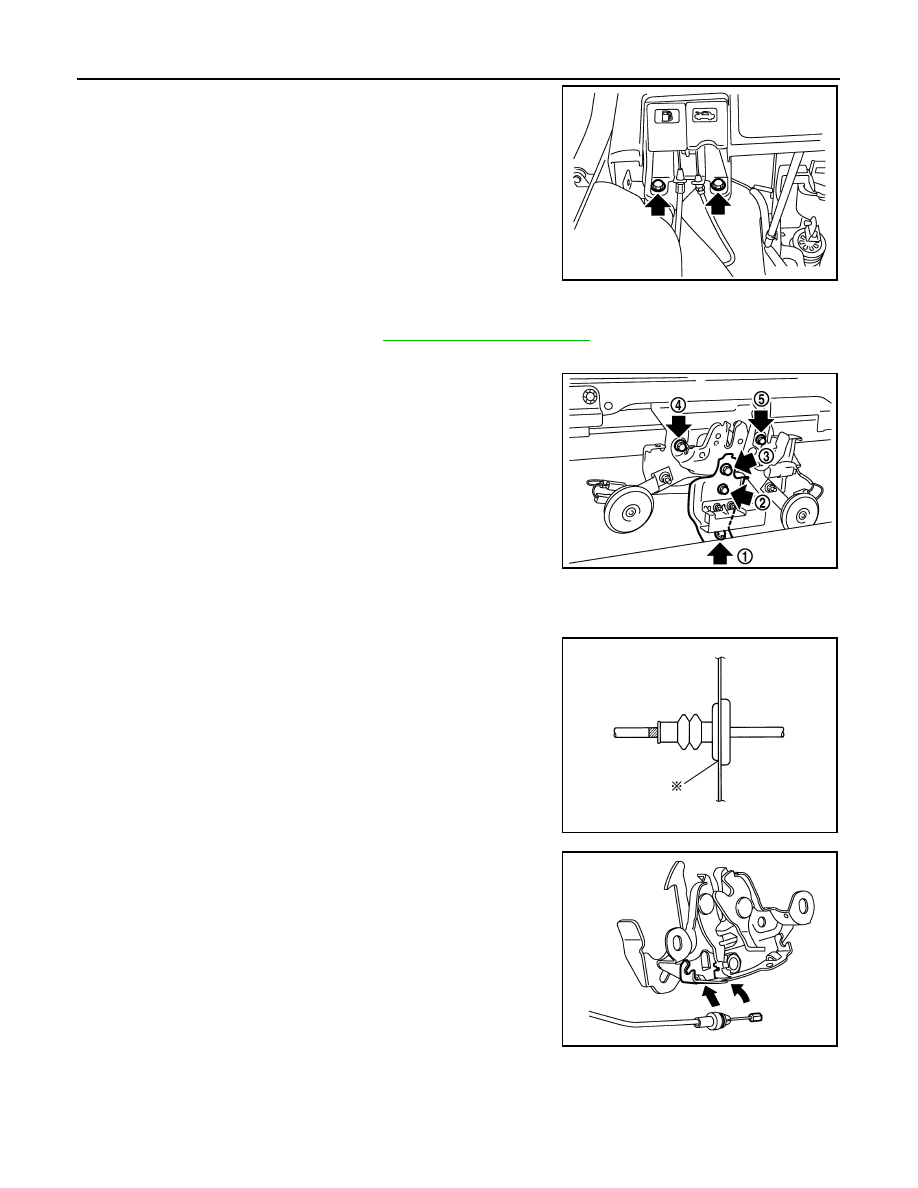
HOOD
5.
Remove hood opener on bottom left of instrument panel, and
then remove hood lock cable.
6.
Remove grommet on lower dashboard, and pull out hood lock
cable from passenger room side.
CAUTION:
While pulling the cable, be careful not to damage (peel)
hood opener cable outer surface on edges of body through
hole.
INSTALLATION
Installation is in the reverse order of removal.
• Perform hood fitting adjustment. Refer to
Hood Lock Reinforcement
When installing hood lock reinforcement, loosen hood bolts, and
then tighten bolts in the order as shown.
Hood Lock Cable
1.
Pull the hood lock cable through the panel hole to the engine compartment.
CAUTION:
Be careful not to bend the cable too much, keeping the
radius 100 mm (3.94 in) or more.
2.
Check that the cable is not offset from the positioning grommet,
and push the grommet into the panel hole securely.
3.
Apply the sealant around the grommet (at * mark).
4.
Install cable securely to lock.
5.
After installing, check hood lock adjustment and hood opener
operation.
Hood Lock Control Inspection
INFOID:0000000001732056
CAUTION:
If the hood lock cable is bent or deformed, replace it.
LIIA2667E
23.6 N·m (2.4 kg-m, 17 ft-lb)
PIIB6513E
PIIB5801E
PIIB6537E