Nissan Tiida C11. Manual - part 1427


  Главная      Nissan     Nissan Tiida C11 - Service Manual


поиск по сайту            


содержание   ..  1425  1426  1427  1428   ..


Nissan Tiida C11. Manual - part 1427


VTL-44

< ON-VEHICLE REPAIR >

[MANUAL AIR CONDITIONER]

BLOWER FAN RESISTOR

BLOWER FAN RESISTOR

Removal and Installation

INFOID:0000000001696536

REMOVAL

1.

Remove the instrument lower finisher and instrument lower cover (LH) for LHD only. Refer to 

IP-11,

"Removal and Installation"

.

2.

Remove the glove box assembly and instrument lower cover (RH) for RHD only. Refer to 

IP-11, "Removal

and Installation"

.

3.

Remove the console side cover. Refer to 

IP-10, "Component Parts"

.

4.

Remove the brake pedal assembly for LHD only. Refer to 

BR-12, "Removal and Installation"

.

5.

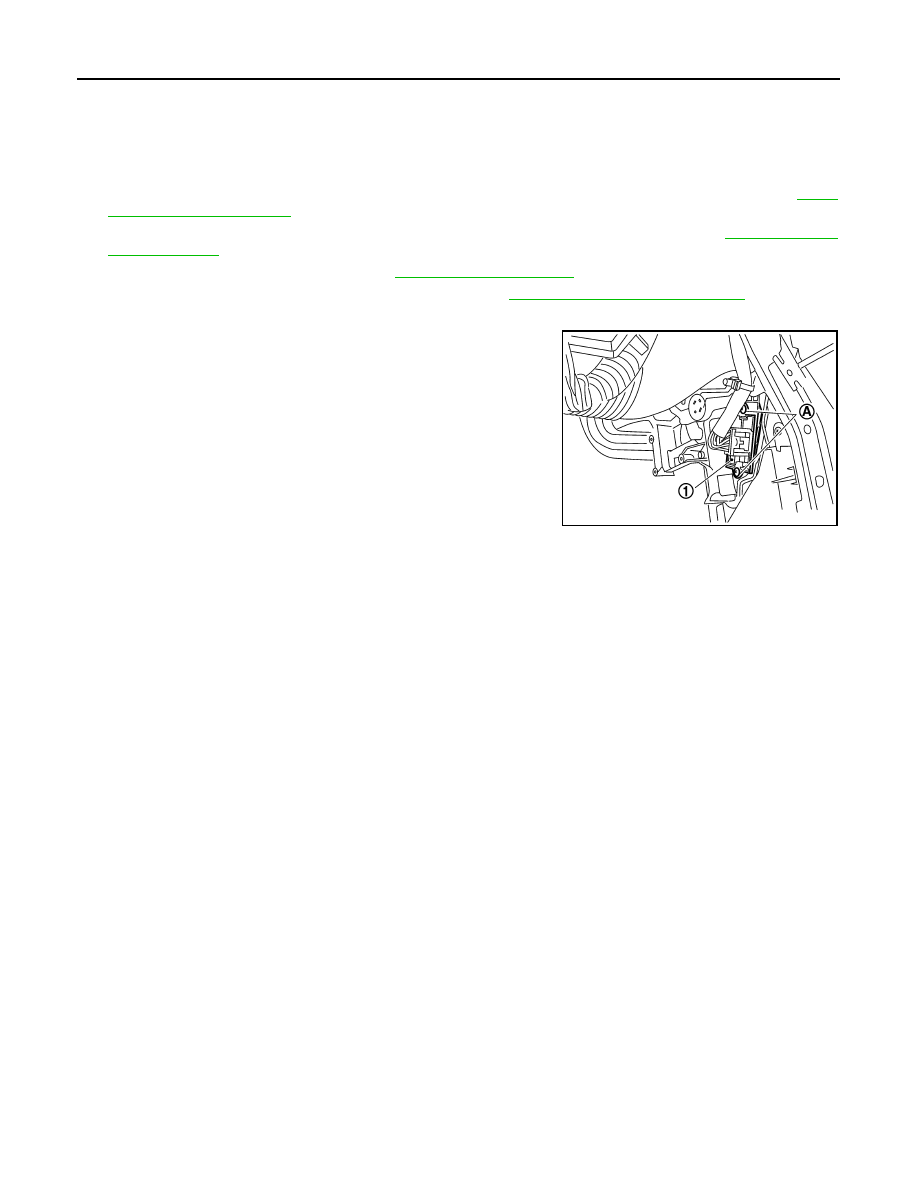
Disconnect the blower fan resistor connector.

6.

Remove the blower fan resistor screws (A), then remove the
blower fan resistor (1).

INSTALLATION

Installation is in the reverse order of removal.

SJIA0656E

INTAKE DOOR

VTL-45

< ON-VEHICLE REPAIR >

[MANUAL AIR CONDITIONER]

C

D

E

F

G

H

J

K

L

M

A

B

VTL

N

O

P

INTAKE DOOR

Intake Door Cable Adjustment

INFOID:0000000001696537

1.

Remove the instrument lower finisher and instrument lower cover (LH) for LHD only. Refer to 

IP-11,

"Removal and Installation"

.

2.

Remove the glove box assembly and instrument lower cover (RH) for RHD only. Refer to 

IP-11, "Removal

and Installation"

.

3.

Remove outer cable of intake door cable (1) from clamp (A).

4.

Set intake door lever to REC position.

5.

Push intake door link (2) in the direction shown by the arrow,
and then carefully pull outer cable to controller side, and install
clamp (A).

6.

Operate intake door lever to insure that inner cable moves
smoothly.

CAUTION:

When clamping the outer cable, do not move the inner
cable.

SJIA0650E

VTL-46

< ON-VEHICLE REPAIR >

[MANUAL AIR CONDITIONER]

AIR MIX DOOR

AIR MIX DOOR

Air Mix Door Cable Adjustment

INFOID:0000000001696538

1.

Remove steering member. Refer to 

ST-9, "Removal and Installation"

.

2.

Remove outer cable of air mix door cable (1) from clamp (A).

3.

Set temperature control dial to full cold position.

4.

Push air mix door lever (2) in the direction shown by arrow, and
then carefully pull outer cable toward controller side, and install
clamp (A).

5.

Operate temperature control dial to insure that inner cable
moves smoothly.

CAUTION:

When clamping the outer cable, do not move the inner
cable.

SJIA1150E

MODE DOOR

VTL-47

< ON-VEHICLE REPAIR >

[MANUAL AIR CONDITIONER]

C

D

E

F

G

H

J

K

L

M

A

B

VTL

N

O

P

MODE DOOR

Mode Door Cable Adjustment

INFOID:0000000001696539

1.

Remove the glove box assembly and instrument lower cover (RH) for LHD only. Refer to 

IP-11, "Removal

and Installation"

.

2.

Remove the instrument lower finisher and instrument lower cover (LH) for RHD only. Refer to 

IP-11,

"Removal and Installation"

.

3.

Remove outer cable of mode door cable (1) from clamp (A).

4.

Set mode control dial to VENT position.

5.

Push main link (2) in the direction shown by the arrow, and then
carefully pull outer cable to controller side, and install clamp (A).

6.

Operate mode control dial to insure that inner cable moves
smoothly.

CAUTION:

When clamping the outer cable, do not move the inner
cable.

7.

Turn mode control dial to each position.

8.

Confirm that discharge air comes out according to the air distribution table. Refer to 

HAC-11, "Discharge

Air Flow"

.

SJIA0654E


содержание   ..  1425  1426  1427  1428   ..