Nissan Tiida C11. Manual - part 1400


  Главная      Nissan     Nissan Tiida C11 - Service Manual


поиск по сайту            


содержание   ..  1398  1399  1400  1401   ..


Nissan Tiida C11. Manual - part 1400


TRANSAXLE ASSEMBLY

TM-651

< DISASSEMBLY AND ASSEMBLY >

[5MT: RS5F91R]

C

E

F

G

H

I

J

K

L

M

A

B

TM

N

O

P

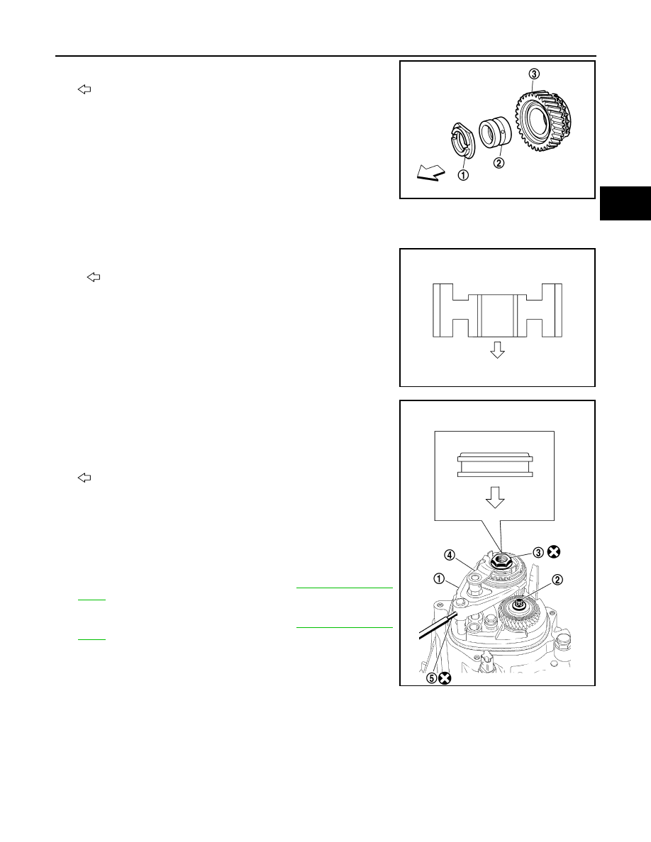
35. Install adapter plate (1), bushing (2) and 5th input gear (3) to

input shaft.

: Transaxle case side

CAUTION:

Be careful with the orientation of adapter plate.

36. Install 5th baulk ring, 5th-reverse synchronizer hub, 5th-reverse coupling sleeve, lock washer, reverse

synchronizer cone and reverse baulk ring to input shaft.

CAUTION:

• Be careful with the orientation of 5th-reverse synchro-

nizer hub.

: 5th input gear side

37. Set 5th-reverse shift fork (1) and reverse gear assembly (4) to

5th-reverse coupling sleeve, and then assemble input shaft and
5th-reverse fork rod.

CAUTION:

Be careful with the orientation of 5th-reverse coupling
sleeve.

: 5th input gear side

38. Make sure that the shift lever of control shaft assembly is shifted

to 3rd gear position. And then, push in 5th-reverse shift fork (1)
to shift it to 5th gear position.
NOTE:
When it is shifted to the 5th gear and 3rd gear at the same time,
the input shaft and mainshaft may not be rotated.

39. Install mainshaft bolt (2) to mainshaft, and then tighten main-

shaft bolt to the specified torque. Refer to 

TM-635, "Exploded

View"

.

40. Install input shaft nut (3) to input shaft, and then tighten input

shaft nut to the specified torque. Refer to 

TM-635, "Exploded

View"

.

41. Install retaining pin (5) to 5th-reverse shift fork using a pin

punch.

PCIB1555E

PCIB1556E

PCIB1641E

TM-652

< DISASSEMBLY AND ASSEMBLY >

[5MT: RS5F91R]

TRANSAXLE ASSEMBLY

42. Shift the shift lever (1) of control shaft assembly to neutral posi-

tion. And then, pull 5th-reverse shift fork to shift it to neutral posi-
tion. 

43. Install O-ring to rear housing and then install them to transaxle

case. Tighten bolts to the specified torque. Refer to 

TM-635,

"Exploded View"

.

CAUTION:

• Rear housing oil channel is inserted to input shaft. There-

fore, when installing rear housing, install it to axial direc-
tion of input shaft.

• Be careful to pinch O-ring when installing rear housing.

44. Install CSC (1) to clutch housing. Refer to 

TM-635, "Exploded

View"

.

45. Install gaskets onto drain plug and filler plug, and then install

them to clutch housing and transaxle case. Refer to 

TM-635,

"Exploded View"

.

CAUTION:

• Do not reuse gasket.
• After oil is filled, tighten filler plug to specified torque.

SCIA7130E

PCIB1558E

PCIB1523E

INPUT SHAFT AND GEAR

TM-653

< DISASSEMBLY AND ASSEMBLY >

[5MT: RS5F91R]

C

E

F

G

H

I

J

K

L

M

A

B

TM

N

O

P

INPUT SHAFT AND GEAR

Exploded View

INFOID:0000000001381697

Refer to 

TM-635, "Exploded View"

.

Disassembly

INFOID:0000000001381698

Refer to 

TM-639, "Disassembly"

 for dissassembly procedure.

Assembly

INFOID:0000000001381699

Refer to 

TM-645, "Assembly"

 for assembly procedure.

Inspection

INFOID:0000000001381700

INPUT SHAFT AND GEARS

Check items below. If necessary, replace them with new ones.
• Damage, peeling, dent, uneven wear, bending, and other non-

standard conditions of the shaft.

• Excessive wear, damage, peeling, and other non-standard condi-

tions of the gears.

SYNCHRONIZER

Synchronizer

Check items below. If necessary, replace them with new ones.
• Damage and excessive wear of contact surfaces of coupling

sleeve, synchronizer hub.

• Coupling sleeve and synchronizer hub must move smoothly.

• If any crack, damage, or excessive wear is found on cam face of

baulk ring or working face of insert, replace it.

BEARING

PCIB0987J

SCIA1753J

SCIA0608J

TM-654

< DISASSEMBLY AND ASSEMBLY >

[5MT: RS5F91R]

INPUT SHAFT AND GEAR

Check for damage and rough rotation of bearing. If necessary,
replace with new one.

MTF0041D


содержание   ..  1398  1399  1400  1401   ..