Nissan Tiida C11. Manual - part 1399


  Главная      Nissan     Nissan Tiida C11 - Service Manual


поиск по сайту            


содержание   ..  1397  1398  1399  1400   ..


Nissan Tiida C11. Manual - part 1399


TRANSAXLE ASSEMBLY

TM-647

< DISASSEMBLY AND ASSEMBLY >

[5MT: RS5F91R]

C

E

F

G

H

I

J

K

L

M

A

B

TM

N

O

P

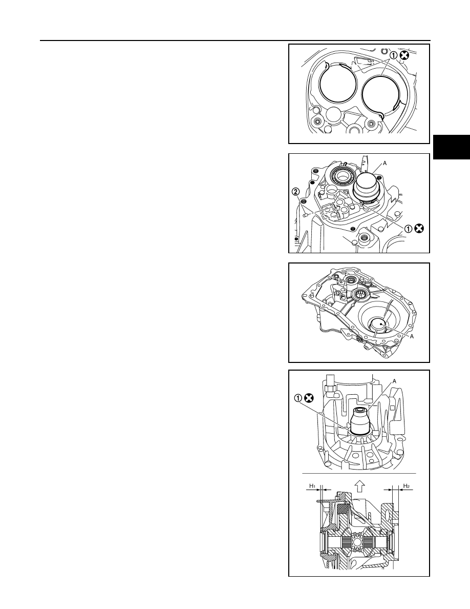
13. Install snap ring (1) to transaxle case as shown in the figure. 

CAUTION:

Be careful with the orientation of snap ring.

14. Using Tool (A), with snap rings (1) stretched, press in input shaft

rear bearing and mainshaft rear bearing into transaxle case.

CAUTION:

Make sure that snap ring is installed to bearing groove
properly.

15. Install check balls (2) to transaxle case. 

16. Install differential side bearing outer races until it is flush with

end face of clutch housing and transaxle case using Tool (A).

17. Install differential side oil seals (1) to clutch housing and tran-

saxle case using Tool (A).

PCIB1547E

Tool number

A: ST35300000

PCIB1548E

Tool number

A: KV32300QA

PCIB1549E

Tool number

A: ST27862000

Dimension “H

1

: 5.7 - 6.3 mm (0.224 - 0.248 in)

Dimension “H

2

: 16.4 - 17.0 mm (0.646 - 0.669 in)

PCIB1550E

TM-648

< DISASSEMBLY AND ASSEMBLY >

[5MT: RS5F91R]

TRANSAXLE ASSEMBLY

18. Install final drive assembly (1) to clutch housing.

19. Install dowel pins (2) and magnet to clutch housing.

20. Install reverse gear assembly onto clutch housing, and then

install retaining pin (1) to reverse gear assembly.

21. Set 1st-2nd fork rod assembly (1) to mainshaft assembly (2),

and then install them to clutch housing.

22. Install lock pins (1) to clutch housing.

23. Install 3rd-4th fork rod assembly (1), 3rd-4th coupling sleeve (2)

and input shaft assembly (3) according to the following.

a.

Lift up 1st-2nd fork rod (4), and then maintain neutral position.

b.

Set 3rd-4th fork rod assembly (1) to 3rd-4th coupling sleeve (2),
and then install it together with input shaft assembly (3) to clutch
housing.

CAUTION:

• Set lock pin (3rd-4th fork rod side) to 1st-2nd fork rod

groove, and then install 3rd-4th fork rod assembly.

PCIB1533E

PCIB1644E

PCIB1532E

PCIB1640E

PCIB1628E

TRANSAXLE ASSEMBLY

TM-649

< DISASSEMBLY AND ASSEMBLY >

[5MT: RS5F91R]

C

E

F

G

H

I

J

K

L

M

A

B

TM

N

O

P

• Be careful with the orientation of 3rd-4th coupling sleeve.

(A): 4th main gear
(B): 3rd main gear

• Install 3rd input gear of input shaft assembly so that it is

lower than reverse main gear of 3rd-4th coupling sleeve.

c.

Install springs and Insert keys to 3rd-4th synchronizer hub.

d.

Install 4th baulk ring.

24. Install 5th-reverse fork rod (1) according to the following.

a.

Lift the gear of the reverse gear assembly (2) up.

b.

Temporarily install 5th-reverse fork rod (1) to clutch housing.

c.

Push down gear of reverse gear assembly (1), and then install
5th-reverse fork rod (2) to clutch housing.

CAUTION:

Set lever of 5th-reverse fork rod so as to align with reverse
gear assembly groove (

).

25. Install 4th main gear (2) and washer (1) to mainshaft.

CAUTION:

Install the washer with the convex side facing the rear side
of the transaxle.

26. Pull down 3rd-4th shift fork, and then shift 3rd-4th coupling

sleeve to 3rd gear side.

PCIB1551E

MCIB0061E

PCIB1629E

PCIB1552E

PCIB1529E

TM-650

< DISASSEMBLY AND ASSEMBLY >

[5MT: RS5F91R]

TRANSAXLE ASSEMBLY

27. Shift the shift lever (1) of control shaft assembly to 3rd gear posi-

tion.
NOTE:
• If not, the transaxle case cannot be removed from clutch hous-

ing.

• 3rd gear position means that the shift lever of control shaft

assembly is fully rotated clockwise and it is returned approxi-
mately 10

°

.

28. Install oil gutter to transaxle case.

29. Apply recommended sealant to mating surface of clutch hous-

ing.

CAUTION:

• Remove old sealant adhering to the mating surfaces. Also remove any moisture, oil, or foreign

material adhering to both mating surfaces.

• Check for damage on the mounting surface.
• Apply a continuous bead of liquid gasket to the mounting surface.

30. Install transaxle case to clutch housing. 

(1): Selector 
(2): Shift fork 

CAUTION:

• Do not allow sealant to contact the transaxle case so as

not to break the bead when installing.

• Be careful to align the lever of 5th-reverse fork rod with

reverse gear assembly sleeve.

NOTE:
If installation is difficult, gently return shift lever of control shaft
assembly counterclockwise slightly.

31. Fit shaft with bearing by rotating input shaft. Then, tighten bolts

to the specified torque. Refer to 

TM-635, "Exploded View"

.

32. Apply recommended sealant to threads of position switch and

check ball plug. Then install them to transaxle case and tighten
to the specified torque. Refer to 

TM-635, "Exploded View"

.

33. Apply gear oil to spline of mainshaft and then press in 5th main

gear (1) to mainshaft using a suitable bolt (A) [M10 x 1.0] and
nut (B).

34. Install spread springs to 5th-reverse synchronizer hub.

PCIB1524E

PCIB1553E

PCIB1528E

PCIB1554E


содержание   ..  1397  1398  1399  1400   ..