содержание .. 1383 1384 1385 1386 ..
Nissan Tiida C11. Manual - part 1385
ASSEMBLY
TM-591
< DISASSEMBLY AND ASSEMBLY >
[TYPE 2 (4AT: RE4F03B)]
C
E
F
G
H
I
J
K
L
M
A
B
TM
N
O
P
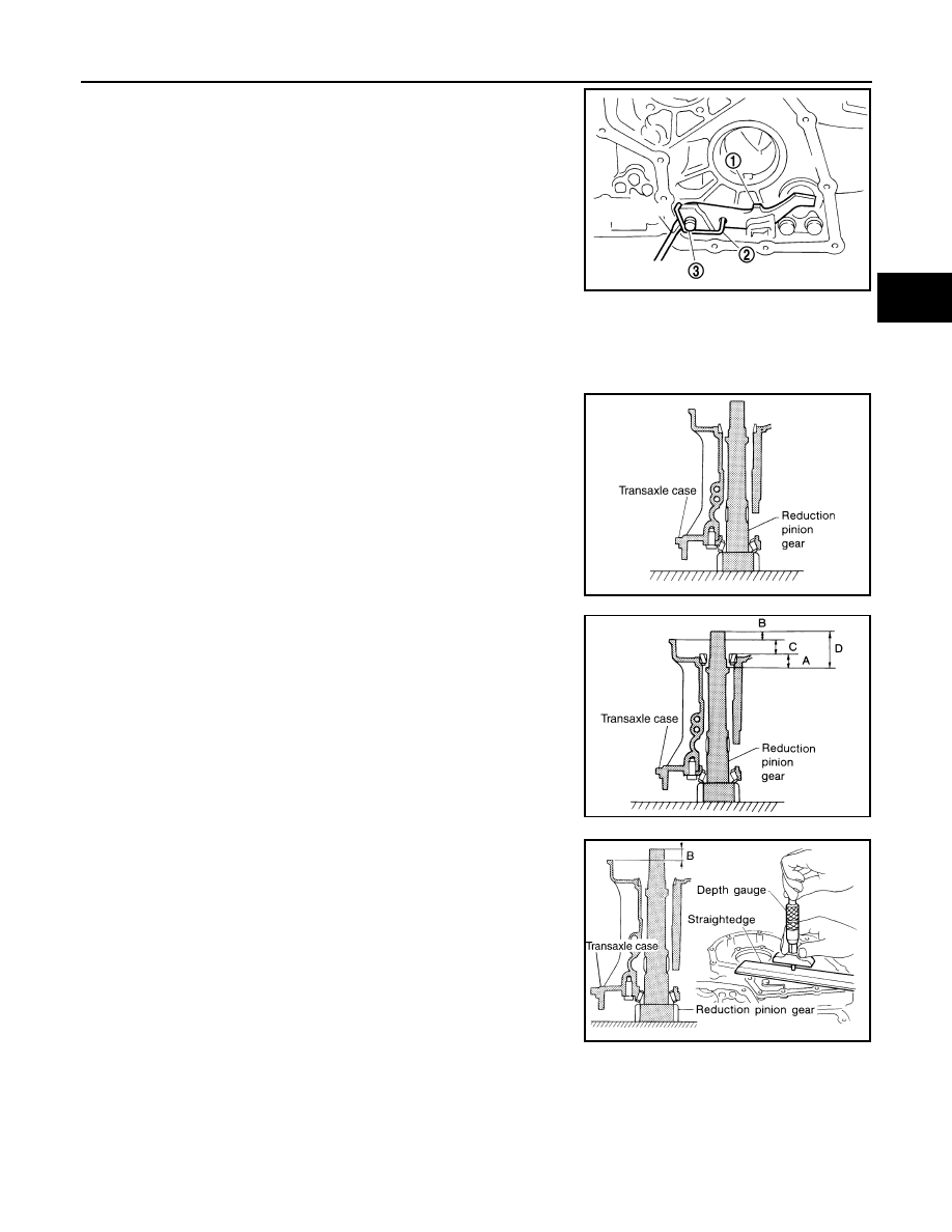
8.
Install return spring (2) on parking shaft (3) and parking pawl (1)
using suitable tool.
Adjustment (1)
INFOID:0000000001731449
REDUCTION PINION GEAR BEARING PRELOAD
1.
Select proper thickness of reduction pinion gear adjusting shim using the following procedures.
a.
Place reduction pinion gear on transaxle case as shown.
b.
Install idler gear bearing outer race on transaxle case.
c.
Place idler gear bearing inner race on outer race.
d.
Measure dimensions “B”, “C” and “D”, and calculate dimension
“A”.
• Measure dimension “B” between the end of reduction pinion
gear and the surface of transaxle case.
• Measure dimension “B” in at least two places, and take
the average.
SCIA6996E
SCIA3623E
“A”:
Distance between the surface of idler gear bear-
ing inner race and the adjusting shim mating
surface of reduction pinion gear.
A = D
−
(B + C)
SCIA3624E
SCIA3625E