содержание .. 1381 1382 1383 1384 ..
Nissan Tiida C11. Manual - part 1383
REPAIR FOR COMPONENT PARTS
TM-583
< DISASSEMBLY AND ASSEMBLY >
[TYPE 2 (4AT: RE4F03B)]
C
E
F
G
H
I
J
K
L
M
A
B
TM
N
O
P
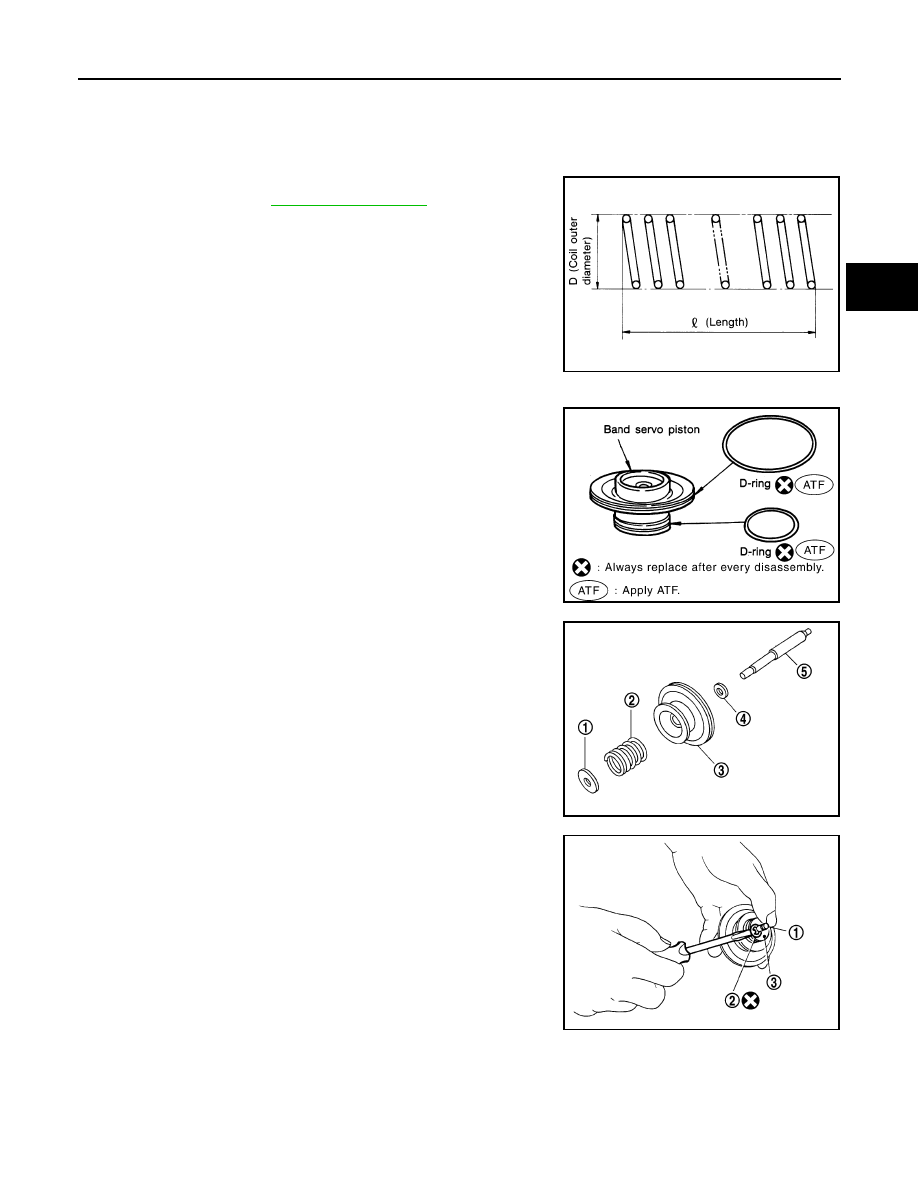
INSPECTION
Pistons, Retainers and Piston Stem
Check the sliding surfaces for damage or excessive wear. Replace if necessary.
Return Springs
• Check each return spring for damage or deformation. Also mea-
sure free length. Refer to
• Replace springs if deformed or fatigued.
ASSEMBLY
1.
Install D-rings to band servo piston.
2.
Install band servo thrust washer (4), band servo piston (3), OD
servo return spring (2) and spring retainer (1) to band servo pis-
ton stem (5).
3.
Place band servo piston stem (1) on a wooden block, and install
E-ring (2) to band servo piston stem (1) while pressing spring
retainer (3) downward.
SAT138D
SCIA3688E
SCIA7054E
SCIA7056E