содержание .. 1382 1383 1384 1385 ..
Nissan Tiida C11. Manual - part 1384
REPAIR FOR COMPONENT PARTS
TM-587
< DISASSEMBLY AND ASSEMBLY >
[TYPE 2 (4AT: RE4F03B)]
C
E
F
G
H
I
J
K
L
M
A
B
TM
N
O
P
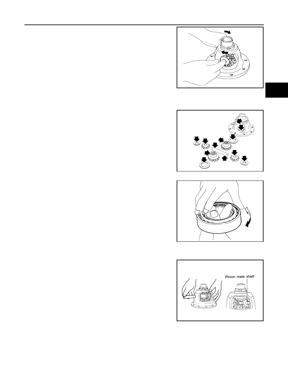
b.
Remove pinion mate shaft from differential case.
c.
Rotate pinion mate gears and pinion mate gear thrust washers
to remove.
d.
Remove side gears and side gear thrust washers from differen-
tial case.
INSPECTION
Gears, Washers, Pinion Mate Shaft and Differential Case
Check the sliding surfaces for wear, seizure, crack or damage.
Replace if necessary.
Bearings
Make sure bearings roll freely and are free from noise, cracks, pitting
or wear. Replace if necessary.
ASSEMBLY
1.
Install pinion mate gears and side gears according to the following procedures.
a.
Attach side gear thrust washers to side gears, then install pinion
mate gear thrust washers and pinion mate gears in place.
CAUTION:
Apply plenty of ATF to each sliding / rotating surface before
assembly.
b.
Set 2 pinion mate gears and thrust washers on the same axis,
and while rotating them simultaneously, align them with the
insert hole of pinion mate shaft on differential case to insert pin-
ion mate shaft.
CAUTION:
After aligning 2 pinion mate gears with side gear teeth and
centering with pinion mate shaft, take pinion mate shaft out
and move pinion mate gears in place while rotating the them simultaneously.
2.
Select side gear thrust washers according to the following procedures.
SAT316D
MTK0135D
SPD715
SAT318D