содержание .. 1377 1378 1379 1380 ..
Nissan Tiida C11. Manual - part 1379
REPAIR FOR COMPONENT PARTS
TM-567
< DISASSEMBLY AND ASSEMBLY >
[TYPE 2 (4AT: RE4F03B)]
C
E
F
G
H
I
J
K
L
M
A
B
TM
N
O
P
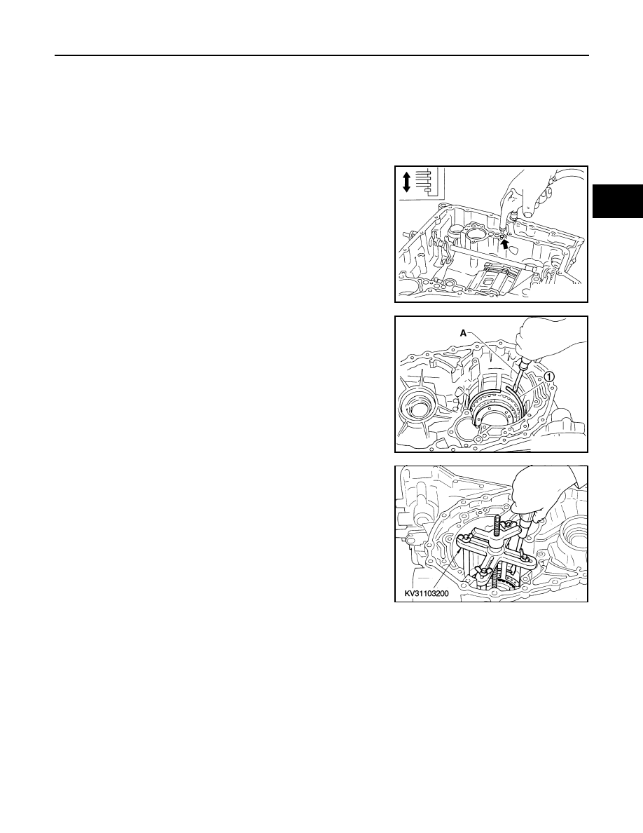
DISASSEMBLY
1.
Check operation of low & reverse brake.
a.
Apply compressed air into oil hole of transaxle case at the loca-
tion as shown.
b.
Check to see that retaining plate moves to snap ring.
c.
If retaining plate does not contact snap ring:
• D-ring might be damaged.
• Seal ring might be damaged.
2.
Remove snap ring (1) using suitable tool (A).
3.
Remove retaining plates, drive plates, driven plates, dish plates.
4.
Set Tool on spring retainer assembly, and remove snap ring
from transaxle case while compressing spring retainer assem-
bly.
CAUTION:
Set Tool directly over return springs.
5.
Remove spring retainer assembly from transaxle case.
CAUTION:
Do not remove return springs from spring retainer.
1.
Seal ring
2.
D-ring
3.
Low & reverse brake piston
4.
Spring retainer assembly
5.
Snap ring
6.
Driven plate
7.
Retaining plate
8.
Driven plate
9.
Retaining plate
10. Snap ring
11.
Drive plate
12. Dish plate
SAT230D
SCIA7039E
SAT242D