содержание .. 1374 1375 1376 1377 ..
Nissan Tiida C11. Manual - part 1376
REPAIR FOR COMPONENT PARTS
TM-555
< DISASSEMBLY AND ASSEMBLY >
[TYPE 2 (4AT: RE4F03B)]
C
E
F
G
H
I
J
K
L
M
A
B
TM
N
O
P
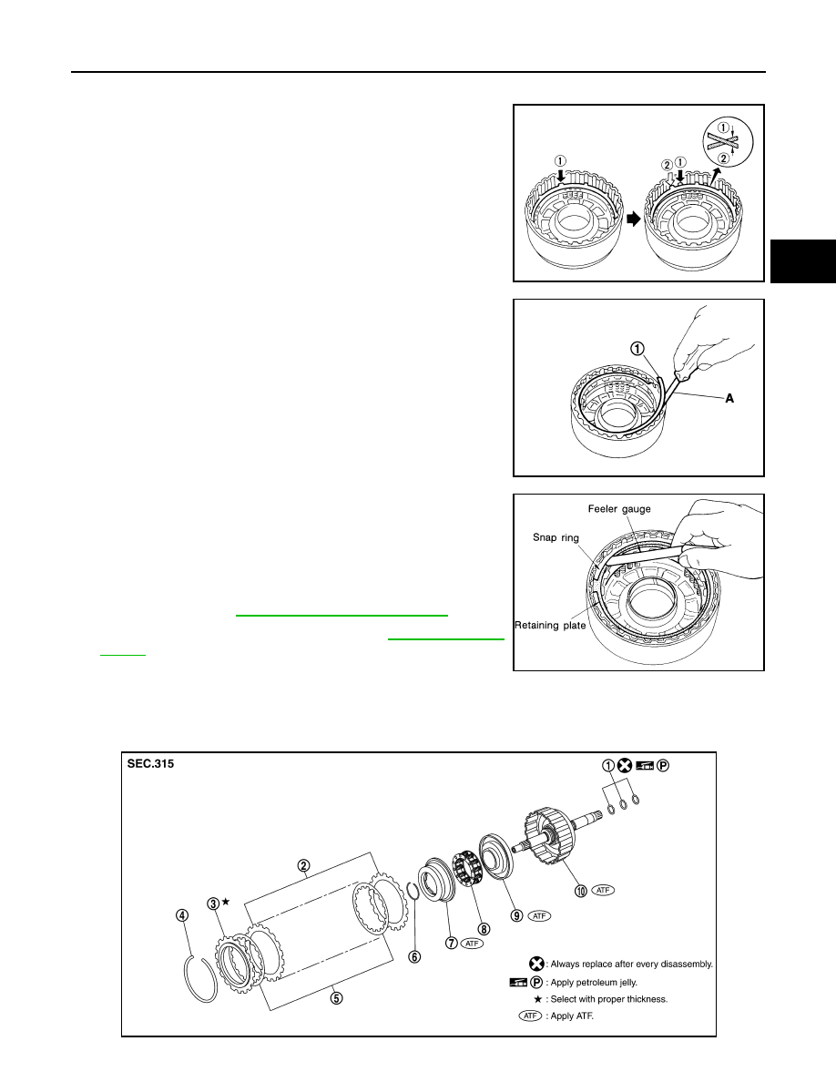
NOTE:
Install two dish plates fitting each installation direction with
reverse clutch drum groove displaced slightly.
6.
Install snap ring (1) using suitable tool (A).
7.
Measure clearance between retaining plate and snap ring using
feeler gauge. If not within allowable limit, select proper retaining
plate.
8.
Check operation of reverse clutch. Refer to
.
High Clutch
INFOID:0000000001731441
COMPONENTS
SAT170D
SCIA7024J
Specified clearance
Standard and allowable limit:
.
SAT174D
SCIA6741E