содержание .. 1351 1352 1353 1354 ..
Nissan Tiida C11. Manual - part 1353
SYSTEM SYMPTOM
TM-463
< SYMPTOM DIAGNOSIS >
[TYPE 2 (4AT: RE4F03B)]
C
E
F
G
H
I
J
K
L
M
A
B
TM
N
O
P
-
Shift valve A
-
Overrun clutch solenoid valve
3.
Disassemble A/T. Refer to
4.
Check the following.
-
Overrun clutch assembly. Refer to
TM-267, "Forward and Overrun Clutches"
.
-
Low & reverse brake assembly. Refer to
.
OK or NG
OK
>> GO TO 10.
NG
>> Repair or replace damaged parts.
10.
CHECK SYMPTOM
TM-186, "Cruise Test - Part 3"
OK or NG
OK
>> INSPECTION END
NG
>> GO TO 11.
11.
CHECK TCM
1.
Check TCM input/output signals. Refer to
TM-22, "Input/Output Signal of TCM"
2.
If NG, recheck TCM pin terminals for damage or loose connection with harness connector.
OK or NG
OK
>> INSPECTION END
NG
>> Repair or replace damaged parts.
TCM Self-Diagnosis Does Not Activate
INFOID:0000000001714365
SYMPTOM:
OD OFF indicator lamp does not come on in TCM self-diagnostic procedure even if the lamp circuit is
good.
DESCRIPTION
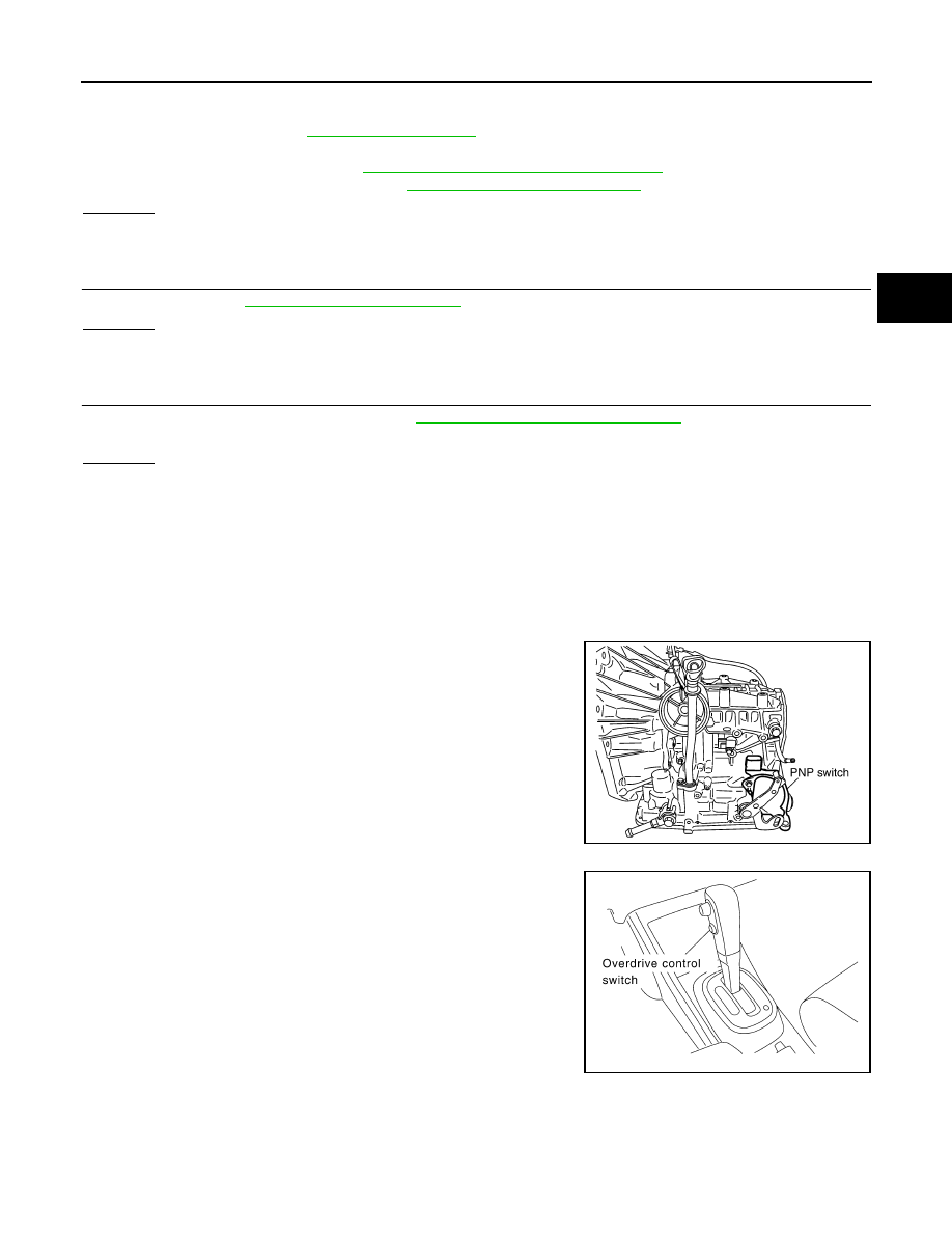
• PNP switch
PNP switch assembly includes a transaxle position switch. The
transaxle position switch detects the selector lever position and
sends a signal to the TCM.
• Overdrive control switch
Overdrive control switch detects the switch position (ON or OFF)
and sends a signal to the TCM.
SCIA7141E
SCIA7142E