содержание .. 130 131 132 133 ..
Nissan Tiida C11. Manual - part 132
CO-46
< ON-VEHICLE REPAIR >
[MR18DE]
THERMOSTAT
• If out of the specification, replace thermostat.
INSTALLATION
Installation is in the reverse order of removal.
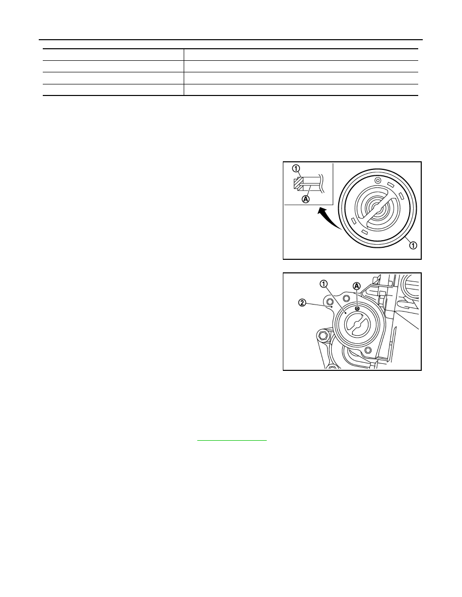
Thermostat
CAUTION:
Replace the rubber ring with a new one.
• Install thermostat while making rubber ring (1) groove fit to thermo-
stat flange (A) around the whole circumference.
• Install thermostat (1) into the thermostat housing (2) with jiggle
valve (A) facing upwards.
Thermostat Housing
CAUTION:
Replace the rubber ring with a new one.
• Securely insert the rubber ring into the mating groove of thermostat housing and install it.
• Install the thermostat housing to the cylinder block without displacing the gasket from the gasket position.
INSPECTION AFTER INSTALLATION
• Check for leaks of engine coolant. Refer to
• Start and warm up the engine. Visually check for engine coolant leaks.
Items
Thermostat
Valve opening temperature
80.5 - 83.5
°
C (177 - 182
°
F)
Maximum valve lift
8 mm/ 95
°
C (0.315 in/ 203
°
F)
Valve closing temperature
77
°
C (171
°
F)
PBIC3315J
PBIC3548J