Nissan Tiida C11. Manual - part 1137


  Главная      Nissan     Nissan Tiida C11 - Service Manual


поиск по сайту            


содержание   ..  1135  1136  1137  1138   ..


Nissan Tiida C11. Manual - part 1137


POWER SUPPLY AND GROUND CIRCUIT

RF-11

< COMPONENT DIAGNOSIS >

C

D

E

F

G

H

I

J

L

M

A

B

RF

N

O

P

COMPONENT DIAGNOSIS

POWER SUPPLY AND GROUND CIRCUIT

SUNROOF MOTOR ASSEMBLY

SUNROOF MOTOR ASSEMBLY : Diagnosis Procedure

INFOID:0000000001724564

SUNROOF MOTOR ASSEMBLY

1.

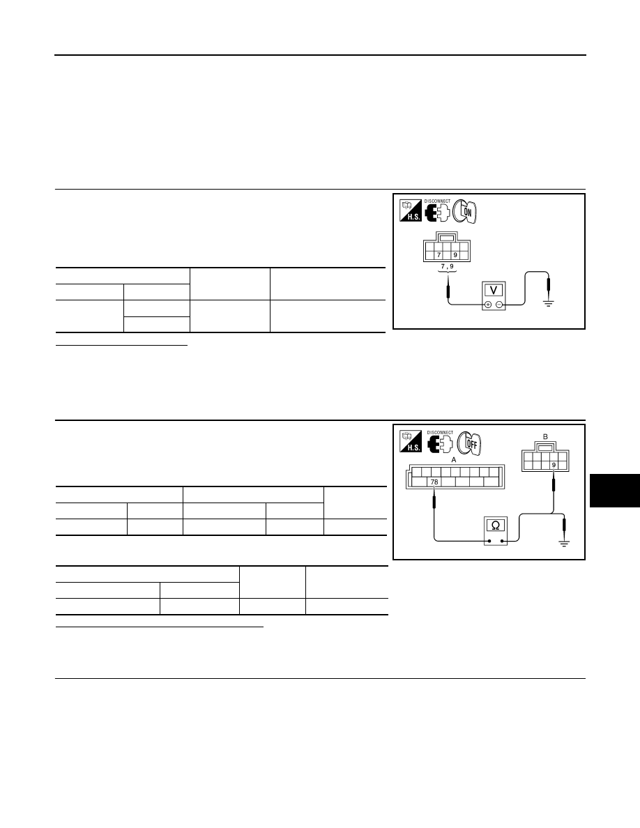
 CHECK SUNROOF MOTOR POWER SUPPLY

1.

Turn ignition switch OFF.

2.

Disconnect sunroof motor assembly connector R4.

3.

Turn ignition switch ON.

4.

Check voltage between sunroof motor assembly connector R4
terminals 7 and 9 and ground.

Is the voltage as specified?

YES

>> GO TO 4

NO, TERMINAL 7>>Check sunroof motor circuit breaker, connector and harness. Refer to PG section, main

wire harness layout.

NO, TERMINAL 9>>GO TO 2

2.

 CHECK SUNROOF MOTOR RETAINED POWER SUPPLY CIRCUIT

1.

Turn ignition switch OFF.

2.

Disconnect BCM connector M20.

3.

Check continuity between BCM connector M20 (A) and sunroof
motor assembly connector R4 (B).

4.

Check continuity between BCM connector M20 (A) and ground.

Are the continuity test results as specified?

YES

>> GO TO 3

NO

>> Repair or replace harness.

3.

 CHECK GROUND CIRCUIT

(+)

(–)

Voltage

Connector

Terminal 

R4

7

Ground

Battery voltage

9

ALKIA1176GB

A

B

Continuity

Connector

Terminal

Connector

Terminal

M20

78

R4

9

Yes

A

Continuity

Connector

Terminal

M20

78

Ground

No

ALKIA1227GB

RF-12

< COMPONENT DIAGNOSIS >

POWER SUPPLY AND GROUND CIRCUIT

1.

Turn ignition switch OFF.

2.

Check continuity between sunroof motor assembly connector
R4 terminal 10 and ground.

Is the continuity test result as specified?

YES

>> Power supply and ground circuits are OK.

NO

>> Repair or replace harness.

SUNROOF MOTOR ASSEMBLY : Special Repair Requirement

INFOID:0000000001724565

1.

 PERFORM INITIALIZATION PROCEDURE

Perform initialization procedure. 
Refer to 

RF-7, "ADDITIONAL SERVICE WHEN REPLACING CONTROL UNIT : Special Repair Requirement"

.

Does the sunroof motor assembly operate properly?

YES

>> Repair is complete.

NO

>> Check fitting adjustment.

Connector

Terminal

Continuity 

R4

10

Ground

Yes

ALKIA1178GB

SUNROOF SWITCH CIRCUIT

RF-13

< COMPONENT DIAGNOSIS >

C

D

E

F

G

H

I

J

L

M

A

B

RF

N

O

P

SUNROOF SWITCH CIRCUIT

Description

INFOID:0000000001724566

A circuit breaker supplies constant battery power to the sunroof motor assembly. The BCM supplies retained
power to the sunroof motor assembly when the key is ON or during retained power operation. The open and
close functions of the sunroof motor assembly are controlled by the sunroof switch. 

Component Function Check

INFOID:0000000001724567

1.

 CHECK SUNROOF MOTOR FUNCTION

Do open and close functions operate normally with the sunroof switch?

Is the inspection result normal?

YES

>> Sunroof motor assembly is OK.

NO

>> Refer to 

RF-11, "SUNROOF MOTOR ASSEMBLY : Diagnosis Procedure"

.

Diagnosis Procedure

INFOID:0000000001724568

1.

 CHECK SUNROOF SWITCH INPUT SIGNAL 

1.

Turn ignition switch ON.

2.

Check voltage between sunroof switch connector and ground.

Are the voltage measurements as specified?

YES

>> Sunroof switch is operating normally. 

NO

>> GO TO 2

2.

 CHECK SUNROOF SWITCH CIRCUITS

1.

Turn ignition switch OFF.

2.

Disconnect sunroof motor assembly connector R4 and sunroof
switch connector R6.

3.

Check continuity between sunroof motor assembly connector
R4 (A) and sunroof switch connector R6 (B) and.

4.

Check continuity between sunroof motor assembly connector R4 (A) and ground. 

Are the continuity test results as specified?

YES

>> GO TO 3

NO

>> Repair harness or connector.

Connector

Terminals

Sunroof switch position

Voltage (V)

(Approx.)

(+)

(–)

R6

1

2

CLOSE

0V

Other than above

Battery voltage

3

OPEN

0V

Other than above

Battery voltage

ALKIA1229GB

A

B

Continuity

Connector

Terminal

Connector

Terminal

R4

5

R6

1

Yes

1

3

A

Continuity

Connector

Terminal

R4

5

Ground

No

1

ALKIA1180GB

RF-14

< COMPONENT DIAGNOSIS >

SUNROOF SWITCH CIRCUIT

3.

 CHECK SUNROOF SWITCH

1.

Check continuity between sunroof switch terminals.

Are the continuity test results as specified?

YES

>> Sunroof switch is operating normally.

NO

>> Replace sunroof switch (map lamp assembly). Refer to

XX-XX, "*****"

.

Terminals

Sunroof switch position

Continuity

1

2

CLOSE

Yes

Other than above

No

3

OPEN

Yes

Other than above

No

ALKIA1181GB


содержание   ..  1135  1136  1137  1138   ..