Nissan Tiida C11. Manual - part 110


  Главная      Nissan     Nissan Tiida C11 - Service Manual


поиск по сайту            


содержание   ..  108  109  110  111   ..


Nissan Tiida C11. Manual - part 110


CHG-18

< PREPARATION >

[MR18DE]

PREPARATION

PREPARATION

PREPARATION

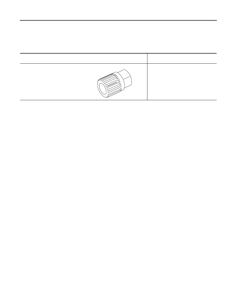
Special Service Tools

INFOID:0000000001691351

Tool number
Tool name

Description

KV10118200 (included in the adapter 
kit: Mot. 1732)
Alternator pulley adapter

Removing and installing alternator pulley

PKIA1241E

CHG

DIAGNOSIS AND REPAIR WORKFLOW

CHG-19

< BASIC INSPECTION >

[MR18DE]

C

D

E

F

G

H

I

J

K

L

B

A

O

P

N

BASIC INSPECTION

DIAGNOSIS AND REPAIR WORKFLOW

Work Flow

INFOID:0000000001724517

OVERALL SEQUENCE

DETAILED FLOW

ALMIA0055GB

CHG-20

< BASIC INSPECTION >

[MR18DE]

DIAGNOSIS AND REPAIR WORKFLOW

NOTE:
To ensure a complete and thorough diagnosis, the battery, starter and generator test segments must be done
as a set from start to finish.

1.

PRELIMINARY INSPECTION

Perform the preliminary inspection. Refer to 

CHG-37, "Inspection Procedure"

.

>> GO TO 2

2.

DISABLE THE POWER GENERATION VOLTAGE VARIABLE CONTROL SYSTEM

Disable the power generation voltage variable control with either of the following procedures.
• After selecting “ENGINE” on the “SELECT SYSTEM” screen of CONSULT-III, set the “ALTERNATOR DUTY”

value to 0 % by selecting “ALTERNATOR DUTY” with “Active Test”. Continue “Active Test” until the end of
inspection. (When the DUTY value is 0 or 100 %, the normal power generation is performed according to the
characteristic of the IC regulator of the generator.)

• Turn the ignition switch OFF, disconnect the battery current sensor connector and leave it disconnected dur-

ing the course of the test.

NOTE:
Running the engine with the battery current sensor disconnected will cause DTC's (P1550-P1554) to set.
After finishing the inspection, connect the battery current sensor connector and erase the self-diagnostic
results history of the engine using CONSULT-III.

>> GO TO 3

3.

DIAGNOSIS WITH STARTING/CHARGING SYSTEM TESTER

Perform the charging system test using Starting/Charging System Tester (J-44373). For details and operating
instructions, refer to Technical Service Bulletin.

Test result

CHARGING SYSTEM NOMAL>>Charging system is normal and will also show “DIODE RIPPLE” test result.
NO CHARGING VOLTAGE>>GO TO 4
LOW CHARGING VOLTAGE>>GO TO 12
HIGH CHARGING VOLTAGE>>GO TO 14
DIODE RIPPLE NORMAL>>Diode ripple is OK and will also show “CHARGING VOLTAGE” test result.
EXCESS RIPPLE DETECTED>>Replace the generator. Perform “DIODE RIPPLE” test again using Starting/

Charging System Tester (J-44373) to confirm repair.

DIODE RIPPLE NOT DETECTED>>GO TO 4

4.

INSPECTION WITH CHARGE WARNING LAMP (IGNITION SWITCH IS ON)

Turn the ignition switch ON.
Does the charge warning lamp illuminate?

YES

>> GO TO 6

NO

>> GO TO 5

5.

TERMINAL“2” (OPEN) CIRCUIT INSPECTION

Check terminal “2” circuit for open circuits. Refer to 

CHG-39, "Diagnosis Procedure"

.

Is the terminal “2” circuit normal?

YES

>> Replace generator.

NO

>> Repair as needed.

6.

INSPECTION WITH CHARGE WARNING LAMP (IDLING)

Start the engine and run it at idle.

Does the charge warning lamp turn OFF?

YES

>> GO TO 9

NO

>> GO TO 7

7.

TERMINAL “2”(SHORT) CIRCUIT INSPECTION

Check terminal “2” circuit for short to ground. Refer to 

CHG-39, "Diagnosis Procedure"

.

Is the terminal “2” circuit normal?

CHG

DIAGNOSIS AND REPAIR WORKFLOW

CHG-21

< BASIC INSPECTION >

[MR18DE]

C

D

E

F

G

H

I

J

K

L

B

A

O

P

N

YES

>> GO TO 8

NO

>> Repair as needed.

8.

TERMINAL“3” CIRCUIT INSPECTION

Check terminal “3” circuit. Refer to 

CHG-40, "Diagnosis Procedure"

.

Is the terminal “3” circuit normal?

YES

>> GO TO 10

NO

>> Repair as needed.

9.

INSPECTION WITH CHARGE WARNING LAMP (ENGINE AT 3,000 RPM)

Increase and maintain the engine speed at 3,000 rpm.

Does the charge warning lamp remain off?

YES

>> GO TO 11

NO

>> GO TO 10

10.

INSPECTION OF GENERATOR PULLEY

Check generator pulley.
Is generator pulley normal?

YES

>> Replace generator. Refer to 

XX-XX, "*****"

.

NO

>> Repair as needed.

11.

TERMINAL “1” CIRCUIT INSPECTION

Check terminal “1””circuit. Refer to 

CHG-38, "Diagnosis Procedure"

.

Is terminal “1” circuit normal?

YES

>> Replace generator. Refer to 

XX-XX, "*****"

.

NO

>> Repair as needed.

12.

TERMINAL “1” CIRCUIT INSPECTION

Check terminal “1” circuit. Refer to 

CHG-38, "Diagnosis Procedure"

.

Is terminal “1” circuit normal?

YES

>> GO TO 13

NO

>> Repair as needed.

13.

INSPECTION OF GENERATOR PULLEY

Check generator pulley.
Is generator pulley normal?

YES

>> Replace generator. Refer to 

XX-XX, "*****"

.

NO

>> Repair as needed.

14.

TERMINAL “3” CIRCUIT INSPECTION

Check terminal“3” circuit. Refer to 

CHG-40, "Diagnosis Procedure"

.

Is the terminal “3” circuit normal?

YES

>> Replace generator. Refer to 

XX-XX, "*****"

.

NO

>> Repair as needed.


содержание   ..  108  109  110  111   ..