содержание .. 1081 1082 1083 1084 ..
Nissan Tiida C11. Manual - part 1083
MWI-22
< FUNCTION DIAGNOSIS >
DIAGNOSIS SYSTEM (METER)
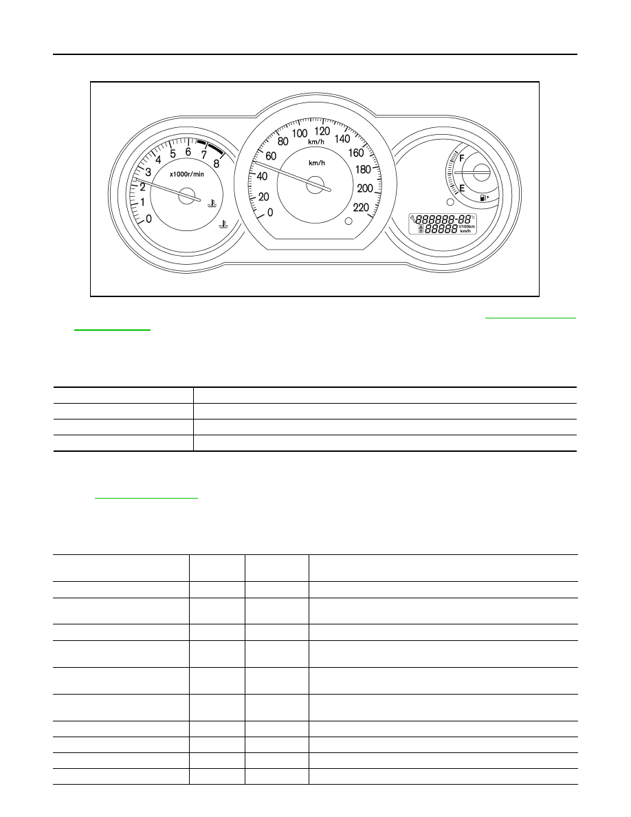
5.
Each meter activates while pressing odo/trip meter switch. (At this time, the low-fuel warning lamp turns
off, low water temperature indicator lamp and high water temperature warning lamp turn on.)
NOTE:
If any of the meter and gages are not activated, replace combination meter. Refer to
CONSULT-III Function (METER/M&A)
INFOID:0000000001374682
CONSULT-III can display each diagnostic item using the diagnostic test modes shown following.
SELF-DIAG RESULTS
Display Item List
.
DATA MONITOR
Display Item List
X: Applicable
AWNIA0164ZZ
METER/M&A diagnosis mode
Description
SELF-DIAG RESULTS
Displays combination meter self-diagnosis results.
DATA MONITOR
Displays combination meter input/output data in real time.
CAN DIAG SUPPORT MNTR
The result of transmit/receive diagnosis of CAN communication can be read.
Display item [Unit]
MAIN
SIGNALS
SELECTION
FROM MENU
Description
SPEED METER [km/h] or [mph]
X
X
Displays the value of vehicle speed signal.
SPEED OUTPUT [km/h] or [mph]
X
X
Displays the value of vehicle speed signal, which is transmitted to
each unit with CAN communication.
TACHO METER [rpm]
X
X
Displays the value of engine speed signal, which is input from ECM.
W TEMP METER [
°
C] or [
°
F]
X
X
Displays the value of engine coolant temperature signal, which is in-
put from ECM.
FUEL METER [lit.]
X
X
Displays the value, which processes a resistance signal from fuel
gauge.
DISTANCE [km] or [mile]
X
X
Displays the value, which is calculated by vehicle speed signal, fuel
gauge and fuel consumption from ECM.
FUEL W/L [ON/OFF]
X
X
Displays [ON/OFF] condition of low-fuel warning lamp.
C-ENG W/L [ON/OFF]
X
Displays [ON/OFF] condition of malfunction indicator lamp.
SEAT BELT W/L [ON/OFF]
X
Indicates [ON/OFF] condition of seat belt warning lamp.
BUZZER [ON/OFF]
X
X
Displays [ON/OFF] condition of buzzer.